Gamatronic Electronic Industries Ltd.
48
Power+ Technical Guide
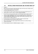
4.2
INSTALLATION PROCEDURE AND SYSTEM START-UP
Operation
1.
Remove rear covers and connect AC input and output power cables to terminals according to markings as shown
in this User Guide and according to connection schematic.
Verify correct phase sequence between board and UPS
2.
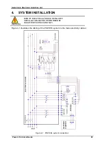
Connect ground lines to busses according to markings as shown in the connection schematics (Figure
4-1 on page 45). Verify secure connections.
3.
Connect the DC power cables of the battery cabinets to the UPS terminals according to markings as shown in
Figure
6-3 on page 68. Connect neutral and ground lines to busses as above.
Verify correct polarity of the connections (+ / N / -) Between the Battery Cabinets C.B.s / Terminals and the UPS
terminals. Auxiliary contacts of Battery C.B.s are connected to UPS Controller inputs “Bat CB” and “Com” as
marked, and as shown in Figure
4.
An external dual-pole / N.C. EPO switch may be connected according to connection schematic.
EPO wiring and switch rating must be rated for at least 5A / 230VAC.
5.
Before connecting power to each system verify again that all connections are secure and are according to
instructions and schematics.
6.
Follow the instructions in section
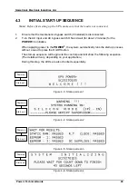
4.3, “Initial Start-up Sequence”, on page 49.
Содержание POWER PLUS
Страница 13: ...Gamatronic Electronic Industries Ltd Power Technical Guide 5 Figure 2 2 Block diagram of a single UPS Module...
Страница 19: ...Gamatronic Electronic Industries Ltd Power Technical Guide 11 Figure 2 8 System controller Block diagram...
Страница 26: ...Gamatronic Electronic Industries Ltd 18 Power Technical Guide Figure 3 4 POWER System Rear View...

