Gamatronic Electronic Industries Ltd.
58
Power+ Technical Guide
5.
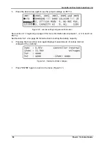
Press the down arrow again to see the jumper settings on PC714.
Figure
5-8. Jumper setting and general information
3.7.1 beginning on page 33 for more information about jumpers 1, 2, 3, 6, and 9 on
PC714.
See Section
6.2.1.2 on page 69 for instruction for setting the battery capacity.
6.
Pressing the down arrow once again displays measurements of various internal
voltages of the controller.
Figure
5-9. Internal controller voltages
7.
Press "ENTER" again to return to the menu (Figure
Содержание POWER PLUS
Страница 13: ...Gamatronic Electronic Industries Ltd Power Technical Guide 5 Figure 2 2 Block diagram of a single UPS Module...
Страница 19: ...Gamatronic Electronic Industries Ltd Power Technical Guide 11 Figure 2 8 System controller Block diagram...
Страница 26: ...Gamatronic Electronic Industries Ltd 18 Power Technical Guide Figure 3 4 POWER System Rear View...

