Gamatronic Electronic Industries Ltd.
Power+ Technical Guide
33
3.7
SYSTEM CONTROLLER CONNECTIONS
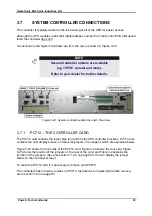
The controller is typically located in the top housing shelf of the UPS for easier access.
Although the UPS modules reads their digital address number from the Control PCB
(discussed
later) the controller does not!
C
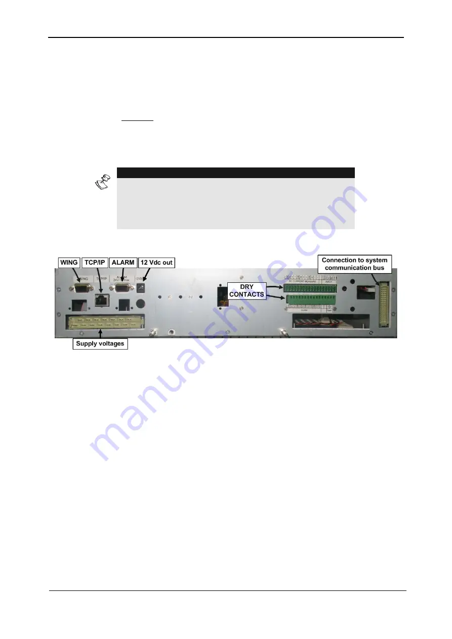
onnections to the System Controller are from the rear, as shown in Figure
NOTE
:
Several Controller options are available
(e.g TCP/IP, cellular and more).
Refer to your dealer for further details.
Figure
3-22: System controller outside the shelf - Rear view
3.7.1
PC714 – THE CONTROLLER CARD
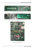
The PC714 card contains the logic chips that perform the UPS controller functions. PC714 also
contains the LCD display screen, and several jumpers, the usage of which are explained below.
3-23 shows the front side of the PC714 card, Figure
3-24 shows the rear side. Figure
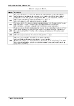
3-25 shows the location of the jumpers on the rear of the card, and Table
function of the jumpers. (See also section
11.4.4 on page 89 for how to display the jumper
status on the controller screen.)
To reach the PC714 card it is necessary to remove card PC575.
The controller's flash memory resides on PC714. Instructions for replacing the flash memory
are in section
Содержание POWER PLUS
Страница 13: ...Gamatronic Electronic Industries Ltd Power Technical Guide 5 Figure 2 2 Block diagram of a single UPS Module...
Страница 19: ...Gamatronic Electronic Industries Ltd Power Technical Guide 11 Figure 2 8 System controller Block diagram...
Страница 26: ...Gamatronic Electronic Industries Ltd 18 Power Technical Guide Figure 3 4 POWER System Rear View...


