30
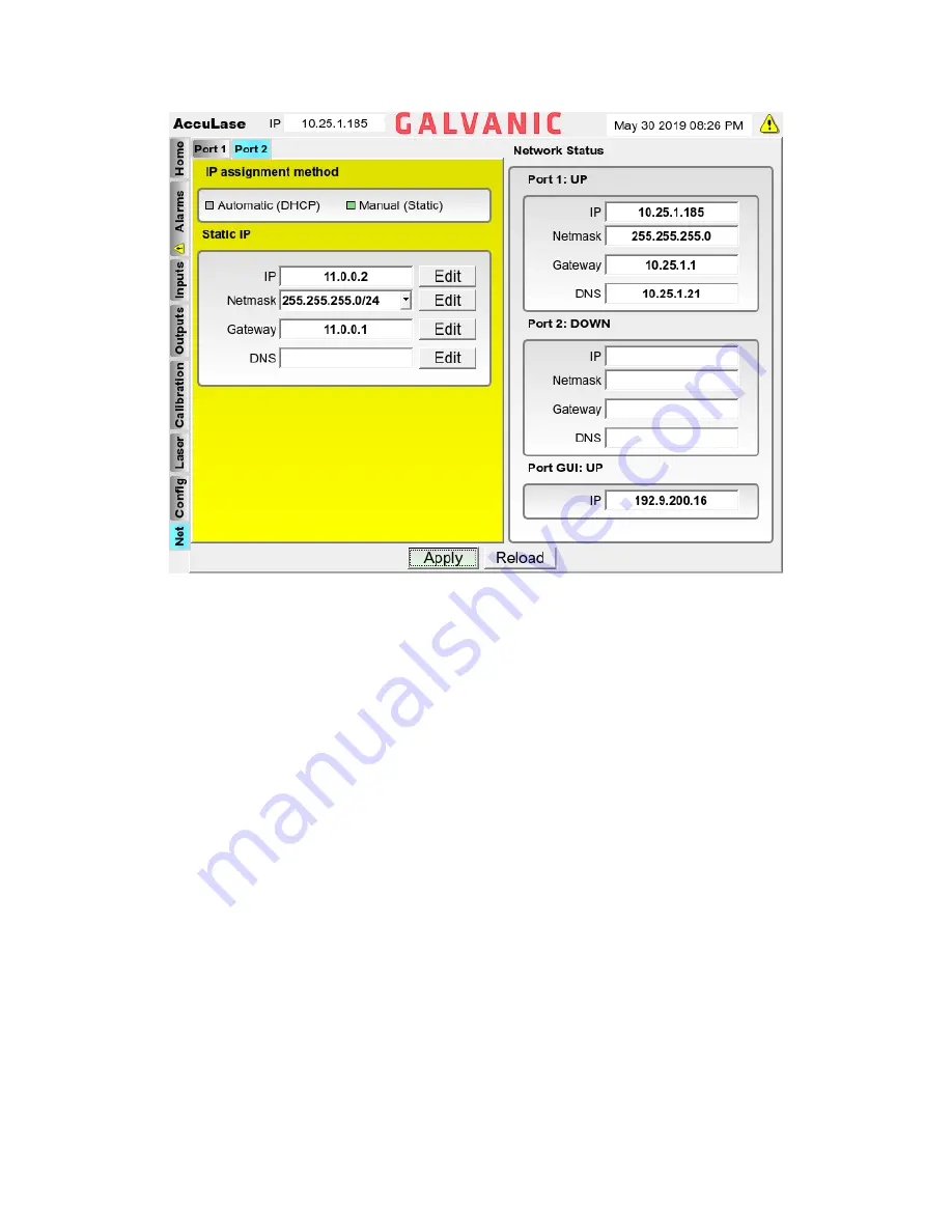
Figure 18: Network Panel (Static IP Address Configuration)
Each field in the Static IP configuration panel must be filled in correctly to ensure that the
AccuLase-GPA™ is able to be accessed remotely via the plant LAN. Obtain the correct settings to
be used in each of the four fields from the plant IT department. To enter in a value into each field,
use the FIELD NEXT / FIELD PREV buttons to navigate to the Edit button beside the field to be
edited, then press ENTER. Use the numerical keys and the decimal key to enter in the correct value
into the field, then press ENTER again.
Once all data has been successfully entered into the fields, use the FIELD NEXT / FIELD PREV
buttons to select the Apply button at the bottom of the screen. Press ENTER to save the Static IP
address configuration to the analyzer. Alternatively, if the user wishes to discard all changes,
selecting the Reload button and pressing ENTER will cause the screen to reload the previously
saved configuration.
3.10.2 Network Status
The Network Status section of the Network panel shows the status of the three Ethernet ports in
the AccuLase-GPA™. Port 1 and Port 2 are both located on the controller board, while Port GUI is
located on the analyzer’s front panel underneath the display. If the port name has the word UP
beside it, this indicates that the port is connected to an external device. If the port name has the
word DOWN beside it, all the configuration fields for that port will be blank. This will indicate that
the port is not connected to an external device. The IP address of the GUI port is not user
configurable – it will always have the IP address indicated in the Port GUI IP field.


