3. VERTICAL MODE
3-6
3.5 Display
Range
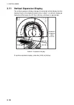
The [RANGE] control selects the detection range. The range selected is
momentarily displayed in large characters at the center of the vertical 1 display.
Range is always displayed at the lower part of the vertical 1 display.
Below are the default ranges (in meters).
Range
Setting
1 2 3 4 5 6
Range
100 200 400 600 800 1000
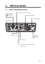
1. Press the [HSV] key to show the gain and range indications of the vertical
mode in yellow.
2. Operate the [RANGE] control to select desired range.
Note:
Ranges may be preset as desired on the PRESET, MEMORY CARD
menu. For further details, see V-SCAN RANGE on page 9-5.
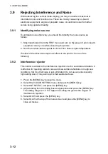
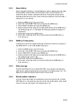
3.6
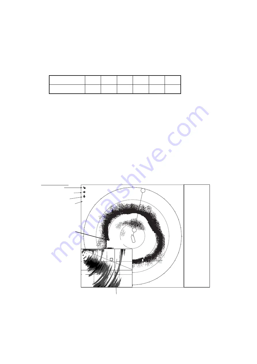
Measuring the Range
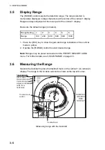
Operate the trackball to place the trackball mark on the vertical 1 (or vertical 2)
display. The range to the location selected is shown at the top left corner.
Trackball mark
N
W
S
E
2000
NUMERIC/
GRAPHIC
DATA
DISPLAY
1000
1500
500
1000
500
2000m
G
V 12
°
8
V
1473m
473m
A
33
°
1547m
Trackball data
Slant range
Horizontal range
Vertical range
Angle to trackball
mark from
horizontal
34
°
56.789N
123
°
45.678E
Trackball mark
position
R 2000m G 8.0
Measuring range with the trackball
Содержание FSV-84
Страница 1: ...COLOR SCANNING SONAR FSV 84 ...
Страница 6: ...SAFETY INSTRUCTIONS iv This page intentionally left blank ...
Страница 34: ...1 OPERATIONAL OVERVIEW 1 18 This page intentionally left blank ...
Страница 158: ...4 SLANT MODE 4 48 This page intentionally left blank ...
Страница 194: ...8 CUSTOMIZING THE EQUIPMENT 8 10 This page intentionally left blank ...

