System
Configuration
290
U41840-J-Z125-7-76
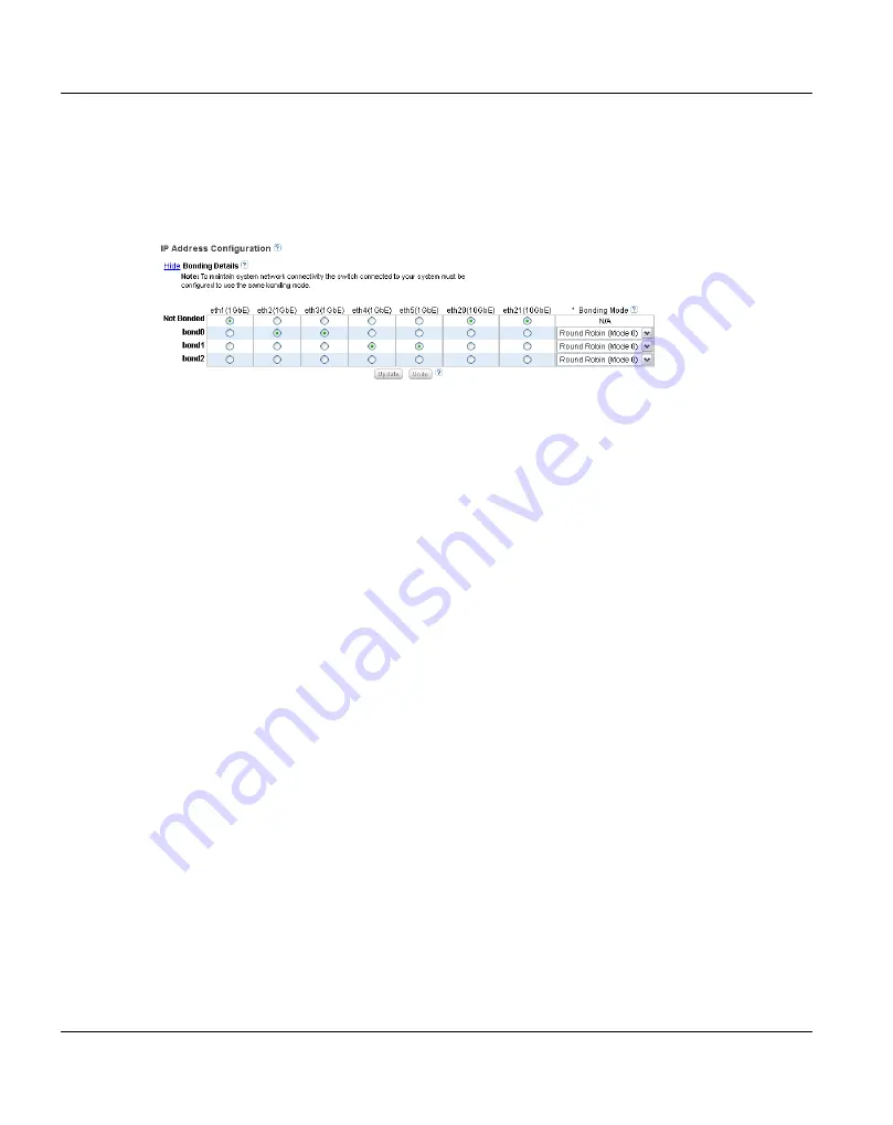
Configuring Bonding Details
Under
IP Address Configuration > Bonding Details
, configure bonded devices (see
Figure 179: Network Page: Bonding Details
1. If necessary, click the
Show
link to show the bonding details table.
2. For each available interface (
bond0
,
bond1
, and so on), select one or more Ethernet
ports with the same link speed to assign to the bond. Or select
Not Bonded
to leave a
port unassigned to any bond.
If no ports are assigned to a bond, the bond cannot be configured. That is, settings
cannot be entered for the bond in the
Interface Details
or
IP Address
tables because
no Ethernet ports are assigned to the port.
All ports assigned to the same interface are bonded together into a single logical port.
For example, if you select
bond0
for port
eth0
and port
eth1
, both ports are bonded
together in the
bond0
interface. A bonded interface can contain two or more ports.
I
All ports associated with a bond must have the same link speed (1GbE or
10GbE).
3. For each bonded interface, specify the bonding mode:
I
To maintain network connectivity, the switch connected to the ETERNUS
CS800 must be configured to use the same bonding mode, except bonding
mode "Active-Backup" shall be used. The best time to change the bonding
mode on the switch is during the next reboot of your system, after saving the
new network settings. Changing the bonding mode on the switch before saving
these settings and rebooting may result in the loss of network connectivity to the
system.
●
Round Robin (Mode 0)
- This option sends Ethernet frames using the bonded
Ethernet ports with a valid MII link. Frames are sent in a round-robin fashion,
starting with the first slave device and then the rest of the devices. This only applies
to the traffic sent from the ETERNUS CS800. The Ethernet switch needs to
aggregate the ports, so the connected ports are treated as a logical port. The
Содержание ETERNUS CS800 S5
Страница 1: ...Edition June 2014 English ETERNUS CS800 S5 V2 3 1 User Guide ...
Страница 14: ...Contents U41840 J Z125 7 76 ...
Страница 30: ...Environmental Protection Important Information 28 U41840 J Z125 7 76 ...
Страница 48: ...Network Configuration System Description 46 U41840 J Z125 7 76 ...
Страница 80: ...Locating the Serial Number Hardware Description and Basic Operations 78 U41840 J Z125 7 76 ...
Страница 116: ...Further Configurations Installing the ETERNUS CS800 S5 Modules 102 U41840 J Z125 7 76 ...
Страница 149: ...Remote Management The Remote Management Console U41840 J Z125 7 76 135 Figure 84 Remote Management Pages Map ...
Страница 150: ...The Remote Management Console Remote Management 136 U41840 J Z125 7 76 ...
Страница 190: ...AIS Connect Configuration Wizards 176 U41840 J Z125 7 76 ...
Страница 200: ...Current Activity Overview Home Page 186 U41840 J Z125 7 76 ...
Страница 301: ...Configuration System U41840 J Z125 7 76 287 Figure 177 Network Configuration ...
Страница 353: ...Configuration Contacts U41840 J Z125 7 76 339 Figure 211 Primary and Secondary Pages ...
Страница 402: ...Reports Replication 388 U41840 J Z125 7 76 ...
Страница 406: ...Hardware Status 392 U41840 J Z125 7 76 Figure 236 System Board Page ...
Страница 432: ...Activity Log Status 418 U41840 J Z125 7 76 ...
Страница 442: ...Service Tickets Alerts 428 U41840 J Z125 7 76 ...
Страница 462: ...Reboot Shutdown Utilities 448 U41840 J Z125 7 76 ...
Страница 470: ...Common Problems and Solutions Troubleshooting 456 U41840 J Z125 7 76 ...
Страница 496: ...Additional Specifications for Scale Mode System Specifications S5 626 U41840 J Z125 7 76 ...
Страница 634: ...Index 634 U41840 J Z125 7 76 ...


