


3
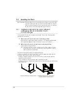
Rack Configuration and Installation
113
E
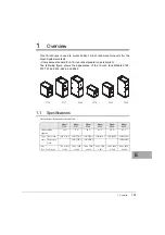
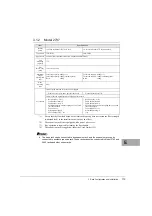
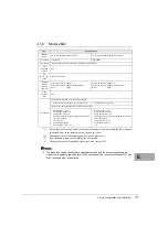
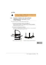
3.1.2
Model 2737
*1)
Ensure that the floor load based on the total rack capacity does not exceed the floor strength
(withstand load) at the installation site (such as an office).
*2)
The expansion rack is not equipped with a pair of side covers.
*3)
Key operation is required for locking the door handle.
*4)
The expansion rack is supplied without the User's Guide (CD).
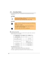
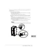
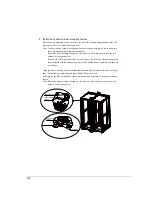
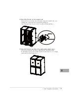
The base rack can be connected to an expansion rack, and the expansion rack can be
connected to another expansion rack. These racks cannot be connected to Model 2742 and
2642 racks and other series racks.
Item
Specifications
Product
name
119-inch rack Model 2737 base rack
19-inch rack Model 2737 expansion rack
Type name
19R-273A2
19R-273B2
Appearance
Coated black (front and rear doors with punched metal finish)
Unit
mounting
capacity
37 U
Size
(W x D x H)
[mm]
700 x 1050 x 1800
Maximum
weight-
bearing load
(kg)
Total rack capacity: 864kg (*1)
Total load capacity: 740kg (excluding rack)
Rack:
124kg
Total rack capacity: 840kg (*1)
Total load capacity: 740kg (excluding rack)
Rack:
100kg
Door
opening
ratio
80%
Accessories
Items already attached to the rack when shipped
・
Front door, rear door, and a pair of side covers
・
Front and rear doors (*2)
Items in their own packages when shipped with the rack
・
Rack door key: 2 (*3)
・
Cable holder (front): 8
・
Cable holder (rear): 8
・
M5 flat head screw and core spring nut: 16 of each
(for cable holder)
・
Cage nut tool
・
Protection bushing: 2
・
User's Guide (CD): 1 set
・
Rack door key: 2 (*3)
・
Cable holder (front): 8
・
Cable holder (rear): 8
・
M5 flat head screw and core spring nut: 16 of each
(for cable holder)
・
Connection kit: 1 set
・
Protection bushing: 2
(*4)
Содержание 19R-261A2
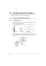
Страница 20: ...20 3 3 後扉の開き方 1 扉用キーを回し解除します ラックハンドルを手前に引き上げ 矢印の方向にハンドルを回転し 手前に引きま す ...
Страница 32: ...32 1 マイナスドライバの先端をケージナットの爪とラック柱の間に挿入して ケージナットの爪に押し込みます 2 マイナスドライバを押し下げて取り外します ...
Страница 72: ...72 5 0 5 0 ࡢሙྜ ࢣ ࣈࣝ ࣝࢲ 0 ࢥ ࣛࢵࢺ 0 ࢧࣛࢿࢪ 5 0 5 0 ࡢሙྜ ࢣ ࣈࣝ ࣝࢲ 0 ࢥ ࣛࢵࢺ 0 ࢧࣛࢿࢪ ...
Страница 73: ...4 ラック設置後の取り扱いについて 73 J 5 0 5 0 ࡢሙྜ ࢣ ࣈࣝ ࣝࢲ 0 ࢥ ࣛࢵࢺ 0 ࢧࣛࢿࢪ 5 0 5 0 ࡢሙྜ ࢣ ࣈࣝ ࣝࢲ 0 ࢥ ࣛࢵࢺ 0 ࢧࣛࢿࢪ ...
Страница 84: ...84 3 背面より M5 サラネジで取り付けプレートとラック およびスタビライ ザー本体を固定します 4 前面の M5 サラネジを本締めします 0 ࢧࣛࢿࢪ ྲྀ ࡅࣉࣞ ࢺ 㠃ഃ ...
Страница 88: ...88 ...
Страница 92: ...92 ...
Страница 95: ...4 ラック設置後の取り扱いについて 95 J 1 コンセントボックス 0U を実装したい箇所にコアラットを取り付けま す コアラットの取り付けは 4 2 コアラットの取り付け 取り外し手順 を参照して ください ...
Страница 100: ......
Страница 186: ......
Страница 188: ......


