


4
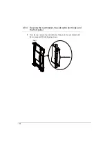
Handling the Rack after Installation
185
E
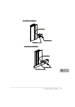
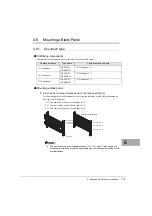
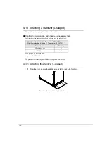
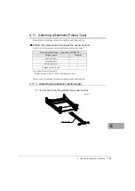
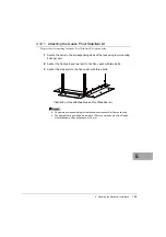
4.12.1 Attaching the Quake Proof Stabilizer kit
The procedure for attaching the Quake Proof Stabilizer Kit is shown below.
1
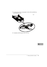
Secure the parts to the corresponding sides of the rack using four mounting
bolts per part.
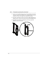
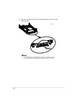
2
Anchor the front part and rear part to the floor, each with two bolts.
3
Anchor the side parts to the floor, each with three bolts.
Customers are requested to provide their own components for floor anchoring.
The floor anchoring hole has a diameter of 20 mm, and the board of the Quake
Proof Stabilizer kit has a thickness of 4.5 mm.
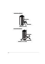
Illustration of the attached Quake Proof Stabilizer kit
Содержание 19R-261A2
Страница 20: ...20 3 3 後扉の開き方 1 扉用キーを回し解除します ラックハンドルを手前に引き上げ 矢印の方向にハンドルを回転し 手前に引きま す ...
Страница 32: ...32 1 マイナスドライバの先端をケージナットの爪とラック柱の間に挿入して ケージナットの爪に押し込みます 2 マイナスドライバを押し下げて取り外します ...
Страница 72: ...72 5 0 5 0 ࡢሙྜ ࢣ ࣈࣝ ࣝࢲ 0 ࢥ ࣛࢵࢺ 0 ࢧࣛࢿࢪ 5 0 5 0 ࡢሙྜ ࢣ ࣈࣝ ࣝࢲ 0 ࢥ ࣛࢵࢺ 0 ࢧࣛࢿࢪ ...
Страница 73: ...4 ラック設置後の取り扱いについて 73 J 5 0 5 0 ࡢሙྜ ࢣ ࣈࣝ ࣝࢲ 0 ࢥ ࣛࢵࢺ 0 ࢧࣛࢿࢪ 5 0 5 0 ࡢሙྜ ࢣ ࣈࣝ ࣝࢲ 0 ࢥ ࣛࢵࢺ 0 ࢧࣛࢿࢪ ...
Страница 84: ...84 3 背面より M5 サラネジで取り付けプレートとラック およびスタビライ ザー本体を固定します 4 前面の M5 サラネジを本締めします 0 ࢧࣛࢿࢪ ྲྀ ࡅࣉࣞ ࢺ 㠃ഃ ...
Страница 88: ...88 ...
Страница 92: ...92 ...
Страница 95: ...4 ラック設置後の取り扱いについて 95 J 1 コンセントボックス 0U を実装したい箇所にコアラットを取り付けま す コアラットの取り付けは 4 2 コアラットの取り付け 取り外し手順 を参照して ください ...
Страница 100: ......
Страница 186: ......
Страница 188: ......