


Page
41
of
42
Fuji Electric Europe GmbH
17.
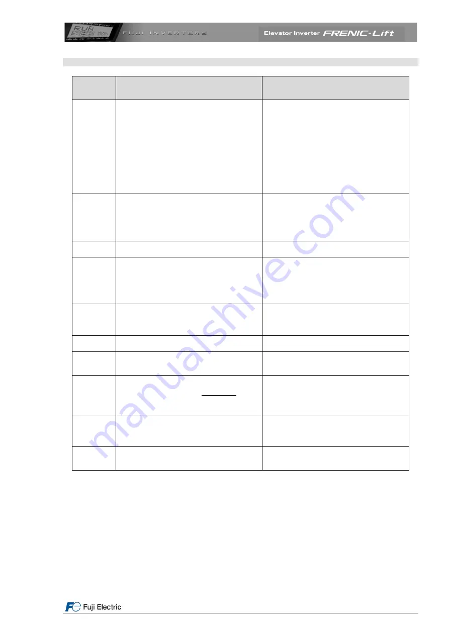
Alarm messages
Alarm
message
Displayed
Description
Possible causes
er6
Operation error
a) Check function L11-L18: One/many
binary combinations are repeated
b) Check brake signal status if BRKE
function is used
c) Check MC signal status if CS-MC
function is used
d) Check function L84
e) Check function L80,L82,L83
f)
If F42=1 and L04=0.00. Pole tuning not
done
g) EN81-1+A3 function is active but
another related function is missed
er7
Error during Auto Tuning / Pole tuning
a) Connection between inverter and motor
interrupted during auto tuning procedure
(main contactors open?)
b) Enable input interrupted
c) Check encoder cable
d) Check encoder
er8
RS 485 Communications error
a) Cable is interrupted
b) High noise level
ere
Speed error (disagreement)
a) Check brake
b) Motor, car or counterweight blocked
c) Check functions L90~L92
d) Current limiter active
e) Has been completed successfully the
pole tuning procedure?
erh
Option card hardware error
a) Option
b) Option card not correctly installed
c) Inverter software version not compatible
with option card
ert
CAN bus communication error
a) CAN bus disconnected from the inverter
b) Electrical noise, connect cable shield
ecf
EN1 and EN2 terminals circuit error
The inverter detects an error on the enable
terminals circuit, and stops itself. Contact
with Fuji Electric.
0s
Motor speed greater than
100
03
32
xF
L
(rpm)
a) Check encoder resolution setting in
function L02
b) Check value of function F03
c) Check value of function P01
d) Check value of function L32
pbf
Charging circuit fault
Fault in the charging circuit of 37 and 45 kW
inverters.
Check power supply in R0/T0 terminals.
Contact with Fuji Electric.
bbe
Brake status monitoring according to EN81-
1+A3
Brake state differs from expected.
For additional information, please contact
Fuji Electric.


