


Page
28
of
42
Fuji Electric Europe GmbH
11. Settings
11.4 Specific settings for induction motors in open loop (geared motors without encoder)
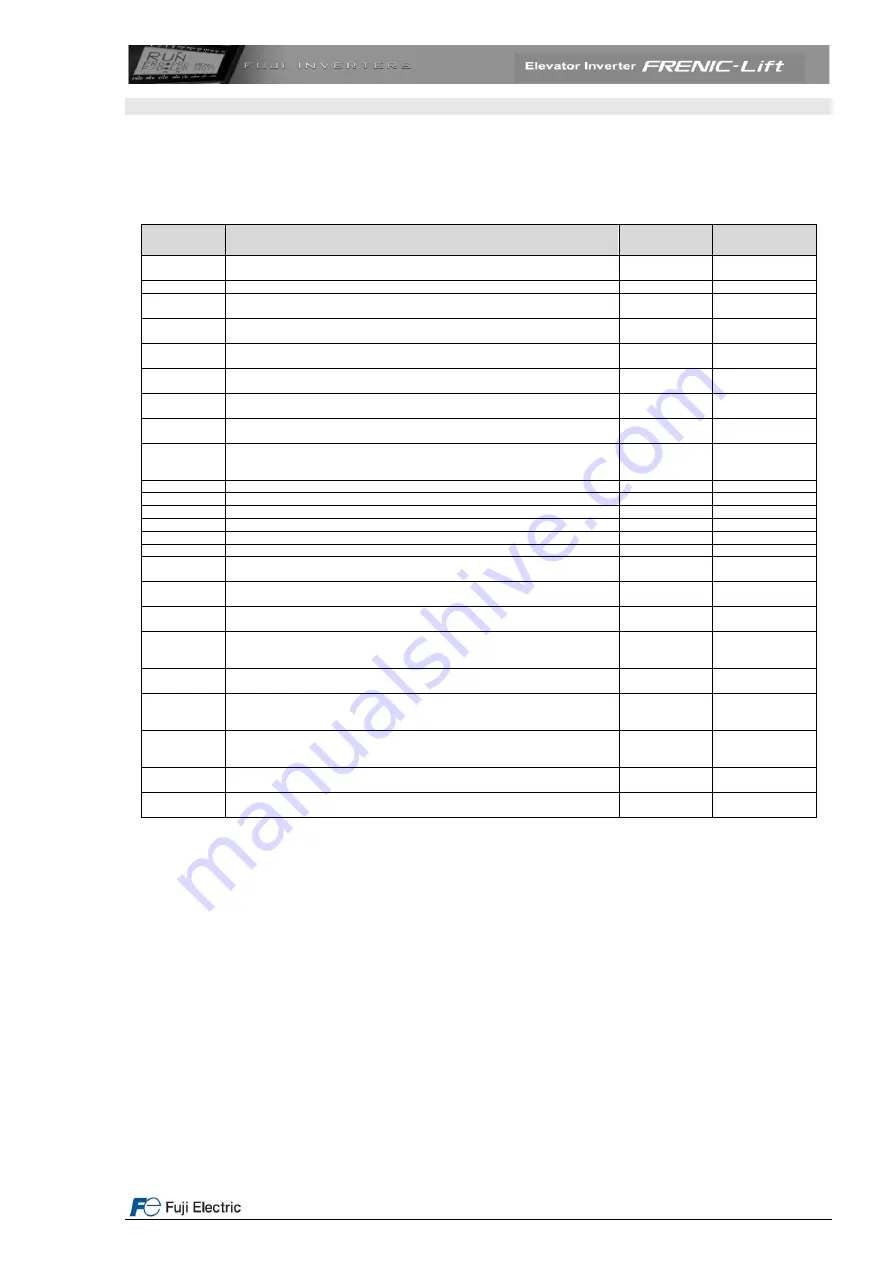
For induction motors auto tuning has to be performed before the first travel. The brake stays applied. To do so, the
parameters described in the table below must be set.
Table 21. Basic setting for induction motor in open loop
Function
Meaning
Factory
setting
Setting
E46
Language setting (clear text function description)
1
Depends on the
country
C21
Speed selection units (C21=0: rpm, C21=1: m/min or C21=2: Hz)
0
2
P01
Motor number of poles from manufacturer data sheet or motor name plate
Must be set before setting F03 value!
4
Depends on the
motor
F03
Motor’s rated speed (from motor’s name plate). The units are always rpm (not
dependant on C21 setting). Normally F03 is motor speed at nominal lift speed
1500 rpm
Depends on the
motor
L31
Maximum linear (in m/min) speed corresponding to F03 value. Used as
linearization factor for speed settings
60.0
Depends on the
installation
F04
Motor’s synchronous speed. The units depend on the setting of function C21.
For 4-pole motors (50Hz) is 1500 r/min, for 6-poles motors (50Hz) is 1000 r/min
1500 rpm
Depends on the
motor
F05
Motor rated voltage from name plate (V)
380 V
Depends on the
motor
F09
Torque boost
0.0%
Depends on the
application
F11
Overload detection level
Depends on the
inverters
capacity
Same as P03
F20
DC
– Braking (Start speed)
0.00 rpm
0.20 Hz
F21
DC
– Braking (Level)
0%
50%
F22
DC
– Braking (Time)
0.00 s
1.00 s
F23
Start speed
0.00 Hz
0.50 Hz
F24
Start speed (Hold time)
0.00 s
1.00 s
F25
Stop speed
3.00 rpm
0.20 Hz
F42
Control type selection (for 37 and 45kW Dynamic torque vector control is not
available)
0
2
P02
Motor rated capacity (power) from name plate in kW
Depends on the
inverter capacity
Depends on the
motor
P03
Motor rated current from name plate in A
Depends on the
inverter capacity
Depends on the
motor
P04
Auto tuning mode.
P04=1: measures P06 and P07 values
P04=3: measures P07, P08 and P12 values and calculates P06 value
0
3
P06
Motor no-load current in A. The Auto tuning procedure calculates, the value of
this function (when P04=3). The calculation overwrites the factory setting
Depends on the
inverter capacity
Automatic
P07
Motor stator resistance (R1) in %. The Auto tuning procedure measures the
value of this function (when P04=1 or 3). The measurement overwrites the
factory setting
Depends on the
inverter capacity
Automatic
P08
Motor stator reactance (X1) in %. The Auto tuning procedure measures the value
of this function (when P04=1 or 3). The measurement overwrites the factory
setting
Depends on the
inverter capacity
Automatic
P12
Slip frequency in Hz. The Auto tuning procedure measures the value of this
function (when P04=3). The measurement overwrites the factory setting
0.00 Hz
Automatic
L83
Delay time for closing (applying) the brake after the speed is under stop speed
(F25)
0.10 s
0.00 s
Auto tuning procedure (executed from input terminals) in 5 steps
To perform the described procedure the enable (EN1&EN2) inputs must be active.
1. Is the motor correctly connected?
2. Turn on inverter mains supply
3.
Please set the functions described in the above table
4. Set function P04 to 3 and press FUNC/DATA
5. Give RUN command to the inverter from the lift controller (normally in INSPECTION mode). The main
contactors will be closed and current will flow through the motor producing some acoustic noise. This
procedure will take some seconds. After this auto tuning procedure is finished.


