


Page
24
of
42
Fuji Electric Europe GmbH
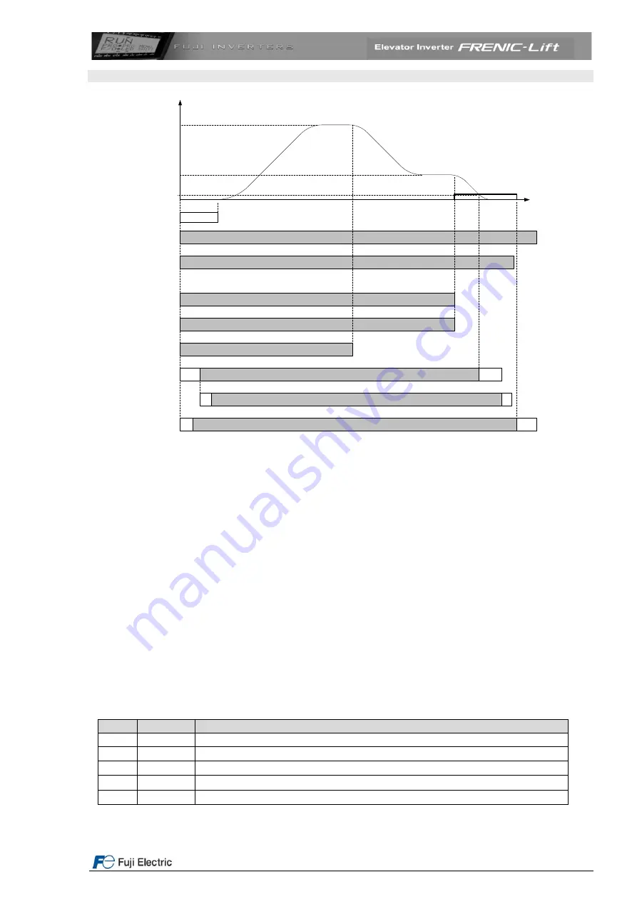
9. Signal timing diagram for normal travel using high and creep speeds
High speed
Creep speed
Stop speed
t1
t
t
t4
Direction inputs
FWD
or
REV
EN1 & EN2
Input
X1
Input
X2
Input
X3
Speed selection
inputs
Mechanical brake
status
Main contactors
t
t3
t2
Figure 25. Signal timing diagram for normal travel.
Sequence description
Start:
By activating FWD (UP) or REV (DOWN) terminal and EN1 and EN2 (enable) terminals, t1 and t2 times start
to run. During that time, terminals X1 to X3 (speed selection) can be activated.
After the completion of time t2 the output of brake control will be activated and the mechanical brake opens
(releases) after some time (delay time to the reaction of contactors, coil
…). After completion of time t1, the
speed set point will be used and the lift will start to move accelerating to reach high speed (normal case).
Stop
:
The terminal X3 will be deactivated by the lift controller (from the internal settings of the controller).
After finishing the deceleration the lift will reach creep speed (set point activated by inputs X1 and X2).
After reaching the floor level, also creep speed will be deactivated. After the deceleration the cabin will reach
zero speed. In this moment t3 begins to run. After time t3, the brake output is deactivated (and brake will be
applied).
To control the main contactors the transistor output Y1 can also be used. With this it is ensured that the
main contactors are opened always after the brake is closed.
Table 18. Description of times shown in figure 25
Time
Function
Description
t
----
Response times (different values) of the brake and main contactors
t1
F24
Time to start to move
t2
L82
Time to release (open) the brake
t3
L83
Time to apply (close) the brake
t4
Controller
Time delay from deactivating enable to opening the main contactors


