Fuji Electric FRENIC-Lift 200 V Series Скачать руководство пользователя страница 27


Page 

27

 of 

42


Fuji Electric Europe GmbH


n

n

V

L

I

L

33

,

4

05


11. Settings 
 

11.3 Specific settings for permanent magnet synchronous motors  
 

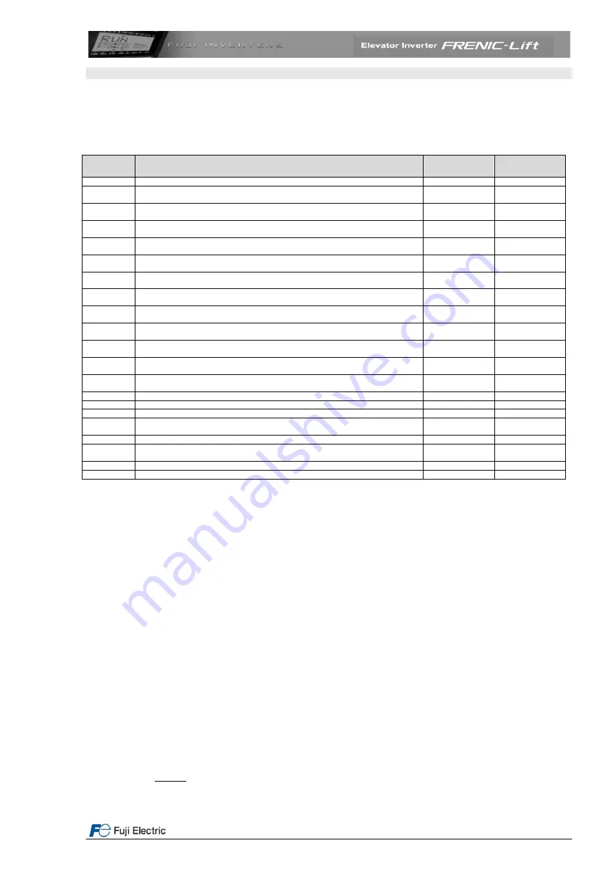
For permanent magnet synchronous motors pole tuning has to be performed before the first travel. The brake stays 
applied. To do so, the parameters described in the table below must be set. 


Table 20. Basic setting for synchronous motor 

Function 

Meaning 

Factory 

setting 

Setting 

H03 

Initialization of factory settings for synchronous motors 

L01 

Encoder type: ECN 1313 EnDat 2.1 or ERN 1387 (or compatible) is possible. See 
information from manufacturer data sheet or encoder name plate 

4 for Endat 2.1 
5 for ERN1387 


Remove power supply from the inverter for a short time (ensure that Keypad is 
completely off) 


E46 

Language setting (clear text function description) 

Depends on the 

country 

C21 

Speed selection units (C21=0: rpm, C21=1: m/min or C21=2: Hz) 

Depends on the 

installation 

P01 

Motor number of poles from manufacturer data sheet or motor name plate 

Must be set before setting F03 value! 

20 

Depends on the 

motor 

F03 

Motor’s maximum speed. The units are always rpm (not dependant on C21 setting). 
Normally F03 is motor speed at nominal lift speed 

60 rpm 

Depends on the 

motor 

L31 

Maximum linear (in m/min) speed corresponding to F03 value. Used as linearization 
factor for speed settings 

60.00 

Depends on the 

installation 

F04 

Motor’s rated speed (from motor’s name plate). The units depend on the setting of 
function C21 

60 rpm 

Depends on the 

motor 

F05 

Motor rated voltage from name plate (V) 

380 V 

Depends on the 

motor 

F11 

Overload detection level 

Depends on the 

inverters capacity 

Same as P03 

P02 

Motor rated capacity (power) from name plate in kW 

Depends on the 

inverters capacity 

Depends on the 

motor 

P03 

Motor rated current from name plate in A 

Depends on the 

inverter capacity 

Depends on the 

motor 

P06 

Motor no-load current in A (for synchronous motor set this function to 0) 

0 A 

0 A 

P07 

Motor stator resistance R1 in % 

5% 

5% 

P08 

Motor stator reactance X1 in % 

10% 

10% 

L02 

Encoder resolution (pulses per revolution) from manufacturer data sheet or name plate 

2048 p/rev 

Depends on the 

encoder 

L04 

Offset angle obtained from pole tuning 

0.00 

Automatic 

L05 

Current loop controller (ACR) P gain 

1.5 

Depends on the 

motor 

L36 

Speed loop controller (ASR) P gain at high speeds 

2.50 

2.00 

L38 

Speed loop controller (ASR) P gain at low speeds 

2.50 

2.00 

 
Pole tuning procedure in 7 steps: 
 
To perform the described procedure the enable (EN1&EN2) inputs must be active. 
 

1.  Are motor and encoder connected properly? 
2.  Apply power to the inverter 

3.  The functions mentioned in the table above must be set. 

Check that the inverter receives the encoder pulses as following: in the keypad go to Menu 

4. I/O Check

 and 

press the down arrow key until you reach the page that shows P1, Z1, P2 and Z2 (8/8). If the motor is not moving, 
the display should show 

+0 p/s

 after P2. Open (release) the brake and turn a little bit the motor. In this moment 

the display should show a number different than 0 (positive or negative depending on the rotation direction). If the 
display shows 

----p/s

 (or 

+0 p/s

 meanwhile the motor is turning) means that no signal is coming from the encoder. 

In this case please check the encoder cable and the connection of the signals. 

4.  Set function 

L03 to 1

 and press FUNC/DATA key.  

5.  Give RUN command to the inverter from the lift controller (normally in RESCUE or INSPECTION mode). The 

main contactors will be closed and current will flow through the motor producing some acoustic noise. This 
procedure will take some seconds. After the procedure was finished correctly the offset value is saved and  
shown in function 

L04

. Write down the displayed value. If Er7 is displayed check the motor and encoder cabling 

and repeat steps 5 and 6. 

6.  If possible, open the brake and let the cabin move some centimetres. 
7.  Perform steps 5 and 6 again. The result in function L04 between different measurements must not    differ more 

than ± 15°. 

L05: Current loop regulator (ACR) P gain calculation  


    L=Motor inductance (minimum value between Ld and Lq) [mH]  

                 V

n

=Motor rated voltage [V] (F05) 


        I

n

=Motor rated current [A] (P03) 


Содержание FRENIC-Lift 200 V Series

Страница 1: ...Starting guide FRENIC Lift Dedicated Inverter for Lift Applications 3 ph 400V 4 0 kW 45 kW 3 ph 200V 5 5 kW 22 kW 1 ph 200V 2 2 kW SG_Lift_EN_1 8 0...

Страница 2: ...ition added on page 39 16 07 2008 J Catal J Catal J Catal 1 3 3 Figure 23 modified Table 11 modified Title changed and text added on page 39 soft start function Alarm messages table modified Tables nu...

Страница 3: ...20 8 Keypad operation 21 8 1 Overview 21 8 2 Keypad menus 22 8 3 Example of function setting 23 9 Signals timing diagram for normal travel using high and creep speeds 24 10 Signals timing diagram for...

Страница 4: ...ion motor without encoder open loop is possible This starting guide includes the important information and explanations about the connection and commissioning of FRENIC Lift for elevator applications...

Страница 5: ...uction motor Do not use it for single phase motors or for other purposes Fire or an accident could occur FRENIC Lift may not be used for a life support system or other purposes directly related to the...

Страница 6: ...on coat may break for any reasons In such a case ensure the signal control wire is protected from making contact with any high voltage cables Doing so could cause an accident or electric shock Connect...

Страница 7: ...ng so could cause electric shock or injuries 2 Conformity to European standards The CE marking on Fuji Electric products indicates that they comply with the essential requirements of the Electromagnet...

Страница 8: ...z 1 phase 380 to 480V 50 60 Hz Input current with DC reactor A 7 5 10 6 14 4 21 1 28 8 35 5 42 2 57 68 5 83 2 Input current without DC reactor A 13 17 3 23 2 33 43 8 52 3 60 6 77 9 94 3 114 Required p...

Страница 9: ...5 to 5 Braking resistor values Maximum braking time s 60 Duty cycle ED 50 Minimum resistor value 5 15 10 7 5 6 4 3 5 33 Options and Standards DC reactor DCRE Optional EMC Filter Optional Safety standa...

Страница 10: ...the terminal block cover and the front cover Figure 2 Mounting the terminal block cover and the front cover Terminal block cover fastening screw PULL Mark Terminal block cover Front cover Front cover...

Страница 11: ...external braking resistor G 2 2 terminals for the connection of the inverter enclosure with the protecting earth Attention It is only allowed to connect one wire to each terminal Please connect the s...

Страница 12: ...Common for Transistor outputs Output signals max voltage is 27 VDC A and B phases available These signals will be available only when using built in encoder interface for 12 15 VDC encoder Available...

Страница 13: ...1 L16 5 101 Intermediate speed 3 C09 1 1 0 L17 6 110 Intermediate speed 4 C10 0 0 1 L18 1 001 High speed C11 5 4 Control terminals description a Analog inputs Using analog inputs the motor speed and t...

Страница 14: ...cribed in the table below Other functions can be set using functions E20 to E23 Lift controller FRENIC Lift 24 V or Optocoupled inputs Y1 Y4 CMY Optocoupled outputs Figure 8 Connection using PNP Sourc...

Страница 15: ...s should not be connected directly they should be connected through a relay or optocoupler e Communication connections keypad DCP 3 PC CANopen FRENIC Lift has one RS485 port and one CAN port available...

Страница 16: ...witches for different function settings On the control board we can find 4 slide switches With these switches different configurations can be set From factory default these switches are configured as...

Страница 17: ...90 shifted UB PO Power supply 12 or 15 VDC 0V CM Common 0 V Z PZ Marker Output signals The signals from A phase and B phase are available as output signals on terminals PAO and PBO to be used by the l...

Страница 18: ...h 2048 pulses rev Other characteristics and application requirements Maximum cable length 20 m Use only shielded cables Figure 12 Option board connection Table 14 OPC LM1 IL connection terminals meani...

Страница 19: ...ion card connection Table 15 Meaning of the connection terminals of OPC LM1 PS1 Terminal name in the option card Signal name of Heidenhain Description P0 Up and Up Sensor Supply voltage 5 V connection...

Страница 20: ...LM1 PR Table 16 Meaning of the connection terminals of OPC LM1 PR Terminals description in the option card Signal name of Heidenhain Description P0 Up and Up Sensor Supply voltage 5 V connection of U...

Страница 21: ...changing the set point frequency in keypad operation Not for elevator applications In Programming mode leave and discard the change in the settings In Programming mode Parameter edit or saving In Oper...

Страница 22: ...TA CHECK menu 3 OPR MNTR OPERATION MONITOR In this menu different operating values can be shown in the LCD display There are 4 different screens showing 4 lines each for example output frequency outpu...

Страница 23: ...ng time can be measured in the real application 8 3 Example of function setting Figure 19 LCD display of the first 4 menus after pressing key Figure 20 Menu selection in this figure maintenance menu i...

Страница 24: ...l start to move accelerating to reach high speed normal case Stop The terminal X3 will be deactivated by the lift controller from the internal settings of the controller After finishing the decelerati...

Страница 25: ...lift from outside the cabin typically RESCUE operation Step by step procedure 1 Ensure that the encoder is connected properly and that the encoder used is suitable for the motor used check also the ch...

Страница 26: ...etting Depends on the inverter capacity Automatic P08 Motor stator reactance X1 in The Auto tuning procedure measures the value of this function when P04 1 or 3 The measurement overwrites the factory...

Страница 27: ...ance R1 in 5 5 P08 Motor stator reactance X1 in 10 10 L02 Encoder resolution pulses per revolution from manufacturer data sheet or name plate 2048 p rev Depends on the encoder L04 Offset angle obtaine...

Страница 28: ...kW Dynamic torque vector control is not available 0 2 P02 Motor rated capacity power from name plate in kW Depends on the inverter capacity Depends on the motor P03 Motor rated current from name plate...

Страница 29: ...f the load condition of the motor In the majority of the cases the value measured by the auto tuning procedure will be correct In some cases the auto tuning procedure cannot be finished correctly due...

Страница 30: ...OP C04 C05 C06 C07 C08 C09 C10 C11 STOP F08 F07 H57 H58 F07 H57 H58 F07 F07 H57 H58 F07 H57 H58 F07 H57 H58 F07 H57 H58 F07 H57 H58 C04 E16 H59 H60 F07 F08 E10 L19 L22 F07 F07 F08 H57 H58 F07 L19 L20...

Страница 31: ...nce from the start of the deceleration to the final floor landing position The time during creep speed has been estimated for 1 s This time depends on the real application High speed C11 Speed ON FWD...

Страница 32: ...2 s Time for decreasing the current inside the motor at the stopping This time must be increased in case the demagnetization process in a synchronous motor makes noise Depends on the installation L82...

Страница 33: ...n L73 0 00 Unbalanced load compensation position proportional gain Depends on the installation L74 0 00 Unbalanced load compensation position derivative gain Depends on the installation L76 0 00 Unbal...

Страница 34: ...direction signal DSD 12 E21 78 78 E22 2 2 E23 57 57 E24 57 Y5A C and 30A B C relay output function 0 Inverter running RUN 2 Speed detected FDT 12 Main contactors control mode 1 SW52 2 78 Door open DO...

Страница 35: ...If the actual frequency is smaller than L30 value then the actual frequency after interrupting the acceleration and reaching constant speed will be held for the time set in function L29 High speed ti...

Страница 36: ...8 S Curve 10 L26 S Curve 8 L25 S Curve 7 L24 S Curve 6 FWD SS1 SS2 SS4 Sdec E13 Acc Dec time 6 E12 Acc Dec time 5 High speed Time Speed ON ON ON ON Zero speed Creep speed Zero speed active Rated speed...

Страница 37: ...Speed Time Stop speed ON FWD SS1 SS2 ON ON SS4 ON Open Brake Creepless Zero speed active Rated speed active L19 S Curve 1 E12 Acc Dec Time 5 L25 S Curve 7 L24 S Curve 6 E13 Acc Dec Time 6 L28 S Curve...

Страница 38: ...t function Digital outputs Y1 to Y4 Y5A C and 30A B C of the inverter can be programmed to RRD Recommended Running Direction function signal This signal gives the recommended direction of travelling m...

Страница 39: ...04 Time ON EN ON SW52 2 Main contactors control ON BRKS Brake control H64 L82 L86 L83 Stop speed F25 H67 H65 Start speed F23 L85 F24 Creep speed C07 L56 Figure 34 Signals timing diagram using soft sta...

Страница 40: ...connection on main contactors 0h1 Inverter heat sink temperature too high a Inverter fan defective b Ambient temperature too high 0h2 External Alarm Digital input programmed with value 9 THR is not ac...

Страница 41: ...counterweight blocked c Check functions L90 L92 d Current limiter active e Has been completed successfully the pole tuning procedure erh Option card hardware error a Option b Option card not correctly...

Страница 42: ...w fujielectric europe com French Branch Fuji Electric Europe GmbH 265 Rue Denis Papin 38090 Villefontaine Tel 33 0 4 74 90 91 24 Fax 33 0 4 74 90 91 75 info france fujielectric europe com www fujielec...

Отзывы: