background image

Freedom Lite Marine Installation Manual Revision 3 


                        P a g e  

9 | 24


Heating may be required in cold conditions to keep the temperature above 0°C, since charging 
the  LiTE  is  not  permitted below 0°C.   Installation  environments  that  regularly exceed  40°C 
should employ cooling if practicable to ensure optimal service life of the LiTE unit.  

Temperature storage or transport of the battery is permitted in the range of -20°C to 45°C, 
however extended storage should be between 0°C and 25°C.  

There  is  no  minimum  requirement  for  spacing  around  the  battery  from  other  objects, 
provided that these objects do not generate heat.  Note, however, that access is required to 
the USB programming port and the CAN Bus sockets and cables exit on the opposite end of 
the SoC and circuit breaker.  

The breaker is rated at IP40 when the lens is open. 

For seaside residential properties it is highly recommended the LiTE Marine units be installed 
in  the  same  ambient  temperature-controlled  environment  as  mentioned  above  with  no 
directed  exposure  to  sea  water.    The  units  are  rated  at  IP65  for  corrosion  and  moisture 
protection.  

4.


Connecting the Freedom LiTE Marine 


4.1.


Power Cables  

The Freedom LiTE is simple to connect to the DC bus or battery inverter.  First, you will connect 
the  battery  positive  and  negative  cables  to  the  inverter  terminals  or  DC  busbar  using  the 
applicable lugs.  

Caution:  

Prior to connecting the positive and negative cables to the inverter or DC busbar, be sure to 
check that the main battery circuit breaker is 

switched off

.  This will ensure that there are no 

short circuits between loose ends of the cables.  

The cables are supplied with the Freedom LiTE Marine, permanently fixed into the unit, and 
secured onto the casing using compression cable glands.  Attached crimp lugs to the ends of 
both cables ensuring that the correct terminal size is used.  Also be sure to match the size of 
the cable to the lug.  The positive cable is red, and the negative cable is black.  See Table 2.1 
for the cable size and quantity fitted to each Freedom LiTE Marine model.  

The cable sizes are based on the inverter or main DC busbar being close to the Freedom LiTE 
battery so that the cable run is less than 5m (note however that the standard cable length is 
1.8m, longer cables available on request).  

Cable runs longer than 5m should be assessed, and larger cables considered for extending the 
Freedom  LiTE  cables,  to  minimise  voltage  drop.    Double  insulation  welding  cable  is 
recommended.  

Содержание LiTE 10/8 Marine

Страница 1: ...rk Honeydew 2040 South Africa www freedomwon co za Technical and Installation Assistance Contact Please contact your Freedom Won Distributor or Reseller Installer for technical and installation support A directory of Distributors and Reseller Installers is available at www freedomwon co za For advanced support please contact support freedomwon co za Revision 3 25 July 2022 ...

Страница 2: ...and industrial applications ranging from 5kWh to 800kWh Larger systems are accommodated by installing multiple units in parallel Models designed for mobile applications including Marine and Mobility are also included in the range line up Freedom Won offer the following ranges in LiFePO4 technology LiTE 12V eTower LiTE Home and Business LiTE Home and Business HV LiTE Marine LiTE Mobility golf carts...

Страница 3: ...pacity of the Freedom LiTE Marine models are provided in Table 2 2 for easy reference The maximum current for each model is governed by the rating of the built in circuit breaker 3 which has been sized below the maximum current capability of the lithium cells This will protect the battery from over current situations There is no significant cell temperature rise during operation and no active cool...

Страница 4: ...Freedom Lite Marine Installation Manual Revision 3 P a g e 3 24 Figure 2 1 Labelled image of the Freedom LiTE Marine 5 4 Labelling corresponds with the text 1 2 3 4 5 6 7 8 9 10 11 12 14 13 ...

Страница 5: ...two people The larger units require lifting equipment of varying degrees for handling and installation as explained later in this document The dimensions given are for the principal outlines of the aluminium housing and exclude items that protrude such as the DC cable glands and handles The DC cables 4 exit the unit through glands located on one end of the casing opposite end to the breaker The ca...

Страница 6: ... optional item and must be specified with the order if the application needs the battery to control relays such as for alternator regulator remote enable On board Management Full battery management system and internal trip protection Human Interfaces USB Plug for Programming and data access with PC main breaker error reset button SoC display error light Protection Shunt Trip Circuit Breaker sized ...

Страница 7: ...nd of Life EoL defined as cell dropping to 60 Two RJ45 sockets 5 are provided one for connecting the CAN interface from the battery to the system controller or directly to the inverter depending on the brand and another for connecting the battery to another battery or for a termination resistor more detail later in the manual A USB socket 6 is fitted adjacent to the breaker for use by technicians ...

Страница 8: ...0Ah 600Ah Table 2 3 Suggested voltage values required for setting up inverters and charge controllers Model 13V 26V 52V Absolute Max Voltage V 14 4 28 1 56 2 Ideal Charge Voltage V 13 9 to 14 2 27 8 to 27 9 55 8 Approx 80 DoD Voltage V 12 6 25 5 51 0 Approx 90 DoD Voltage V 12 2 25 0 50 0 Min Cut out Voltage V 11 5 23 0 47 0 3 Transport Handling and Mounting The Freedom LiTE Marine units are packa...

Страница 9: ...lley or pallet jack 4 Always ensure that lifting equipment and slings are adequately rated for lifting the weight 5 Ensure slings do not exert undue sideways force on the eye bolts 6 Ensure that the eye bolt fixing point shows no signs of damage before lifting 7 Wear personal protective equipment such as safety shoes and gloves while handling and mounting the Freedom LiTE 8 Always ensure that you ...

Страница 10: ...E Marine 4 1 Power Cables The Freedom LiTE is simple to connect to the DC bus or battery inverter First you will connect the battery positive and negative cables to the inverter terminals or DC busbar using the applicable lugs Caution Prior to connecting the positive and negative cables to the inverter or DC busbar be sure to check that the main battery circuit breaker is switched off This will en...

Страница 11: ... Table 4 1 Short Circuit Current for LiTE Marine Models Freedom LiTE Marine 5 4 Marine 10 8 Marine 20 16 Marine 30 24 Short Circuit Current A 1500 2100 3600 4700 The external isolating device required for installations that are required to conform to the CEC of Australia should be designed to withstand these fault levels short circuit current as well as the applicable current rating of the battery...

Страница 12: ...Freedom Lite Marine Installation Manual Revision 3 P a g e 11 24 Figure 4 1 Typical Installation Single Line Diagram ...

Страница 13: ...tion protocol in systems with many devices that must report their status or send commands to other devices on the same network The Freedom LiTE BMS can transmit messages and commands in CAN protocol to provide information to but more importantly to control external devices There are only two wires required in this form of communication namely CAN High and CAN Low In order for an inverter charge co...

Страница 14: ...CAN cable spliced to not require a resistor Most devices operating on CAN have two plugs to connect in and then out again on the CAN Bus The first and the last device in the chain must have a termination resistor plugged into the spare second plug The LiTE resistor plugs are available from the inverter manufacturer and from Freedom Won Where one LiTE is installed or where it is the end of the line...

Страница 15: ...se select a smaller model and install the number that is required to meet the capacity requirements All batteries must be connected to each other using standard LAN Cable Where CAN Bus is used to control the inverter s and or charge controller s and or alternator S the CAN Bus from any battery can be connected to any of the other devices This is achieved by providing two RJ45 socket on the battery...

Страница 16: ...inside the battery Once the BMS has been energised you will observe the SoC display come to life with the SoC level Confirm at this stage that the error light is not illuminated If it is press the reset button on the LiTE if the error returns contact Freedom Won or your Distributor If the Reduced Power light is illuminated do not be concerned it should extinguish after the battery has been charged...

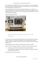
Страница 17: ...t self discharge Figure 6 1 ON and OFF Buttons 7 Settings Required for Setting up Inverters and Charge Controllers The maximum and continuous charge and discharge currents for the respective models are provide in Table 2 1 Ensure that the combination of the mains shore power charger alternator and the Solar Charge Controller SCC does not exceed the maximum continuous charge current Use the voltage...

Страница 18: ...air The Freedom LiTE is sealed with a tamper proof warranty seal It may not be opened by anyone other than Freedom Won and installers or repairers that have been explicitly approved by Freedom Won The warranty on the unit will be void if the seal is damaged or missing If the Freedom LiTE indicates and internal problem please contact Freedom Won or the installer that installed the system If a fault...

Страница 19: ...life expected is 20 years or more For applications where the cost per kWh delivered by the battery during its lifetime is of prime importance i e maximum return on investment we recommend that the battery be sized for an average cycle discharge of 50 DoD In a daily cycling scenario such as for optimal solar self consumption and off grid systems the expected service life is then 20 years or more th...

Страница 20: ...ther a Solar Charger of AC Charger to charge as soon as possible ensure that the loads are switched off 3 Battery has been charged to critically high voltage level usually leaving the battery for an hour will allow the cell levels to drop down within acceptable levels and allow the BMS to be switched on again Ensure that the suspect charge device is not able to charge the battery until you have es...

Страница 21: ...discharge again This reduces the inrush current on the second closing attempt If this does not work after the second attempt investigate the other options Note that closing a breaker onto a DC bus without pre charging is not recommended 3 Short circuit on the DC Bus or faulty inverter or MPPT causing high currents 4 In a system with multiple LiTEs in parallel the reason could be that the battery y...

Страница 22: ...on again investigate what is wrong with the setup that is causing the overcharge events 5 I have switched off the main battery breaker switch to prevent discharge of the battery but the SOC display lights are still on The BMS and SoC display receive power directly from the battery and therefore the OFF Button must be pressed to switch off the internal electronics 6 The inverter will not come on ev...

Страница 23: ...the battery while you make contact for assistance 9 The pack voltage and SoC is within limits but the main breaker still trips seemingly at random This could be caused by many things but is most likely because the current draw is exceeding the battery current limit setting Measure the current with a tong tester clamp meter while drawing your maximum typical load to determine if you are exceeding t...

Страница 24: ...gh there are two explanations 1 the SoC has lost its calibration and the battery needs to be fully charged to regain SoC accuracy This typically occurs if the battery has not received a full charge for several days 2 there is a problem with a cell it may be defective or simply out of balance Please contact Freedom Won for further investigation ...

Отзывы: