Freedom Lite Marine Installation Manual Revision 3
P a g e
4 | 24
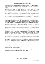
1.
Gross Capacity
2.
80% Capacity recommended for daily cycling (max available is 90%)
3.
Breaker
4.
Power Cables
5.
CAN Bus Sockets x 2 (RJ45) (one socket must contain a termination resistor if end of
line)
6.
USB Programming Port (note in models produced prior to July 2020 the port is a DB9
plug)
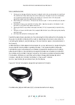
7.
Supplied USB cable
8.
State of Charge Display
9.
Reset Button
10.
On Button
11.
Off Button
12.
Handles for Manual Lifting (larger models have eye bolts)
13.
Moisture protection breaker lens cover
14.
Feet
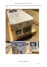
The weight of each model is given in Table 2.1. The Freedom LiTE Marine 5/4 and 10/8 can
manually be lifted with the fitted handles by two people. The larger units require lifting
equipment of varying degrees for handling and installation as explained later in this
document.
The dimensions given are for the principal outlines of the aluminium housing and exclude
items that protrude such as the DC cable glands and handles.
The DC cables [4] exit the unit through glands located on one end of the casing (opposite end
to the breaker). The cable sizes are provided in Table 2.1 for each model. The correct cable
lugs for connecting these leads to the inverter must be in hand when doing an installation. If
there are several inverters, alternators and charge controllers that need to be connected to
the battery it is advisable to install a junction point from which to branch out to all the battery
connected equipment. In boats, these cables could typically be routed to DC busbars in the
power distribution and control console.


