Freedom Lite Marine Installation Manual Revision 3
P a g e
2 | 24
The LiTE Marine range is water and corrosion resistant, rated at IP65, associated with sea
moisture exposure. Note that the product is not suitable for repeated direct exposure to sea
water.
The range is designed with a low profile to fit into height restricted lockers, etc. All models
are supplied standard with plastic feet. It is permissible to stack Marine models on top of
each other, up to three high (this relates to land-based applications).
Table 2.1 provides and overview of the Freedom LiTE Marine range. There are Freedom LiTE
models in the Marine range, as included in Table 2.1, classified in terms of energy capacity.
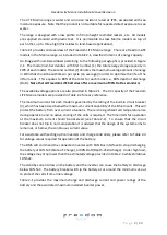
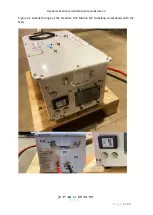
An image with numbered labels pertaining to the following paragraphs is provided in Figure
2.1. The model number denotes with first number [1] the total energy storage capacity in
kWh of each model. The second number [2] denotes the maximum average amount of energy
in kWh that should be withdrawn per cycle (on average) in order to optimise the life of the
lithium cells. This equates to 80% of the total for each model i.e., 80% depth of discharge
(DoD).
Note that all Freedom LiTE batteries offer a maximum of 90% DoD as standard.
The available voltage options are also provided in Table 2.1. The Ah capacity of the Freedom
LiTE Marine models are provided in Table 2.2 for easy reference.
The maximum current for each model is governed by the rating of the built-in circuit breaker
[3], which has been sized below the maximum current capability of the lithium cells. This will
protect the battery from over current situations. There is no significant cell temperature rise
during operation and no active cooling of the cells is required. The time limits for operation
at the maximum current should be observed (see Table 2.1). To ensure that the circuit
breaker does not trip in normal operation it is advised that the design of the system aims to
remain at, or below, the continuous current value.
For assistance with setting up the inverters and charge controllers, please refer to Table 2.3
for voltage values required for operation of the battery.
The BMS will command the connected inverter with CAN Bus interface to stop discharging
the battery at 10% SoC (State-of-Charge), or 90% DoD (Depth-of-Discharge). Under high load,
the voltage may drop lower than the estimated voltage provided in Table 2.3 while still above
10% SoC.
The standby current draw on the battery and the inverter can cause the battery to discharge
below 10% SoC. The battery breaker will trip the battery at or around the minimum cut-out
to protect the cells from under voltage.
Table 2.1 provides the maximum charge and discharge current and power ratings of the
battery and the associated maximum installed inverter power.


