Freedom Lite Marine Installation Manual Revision 3
P a g e
12 | 24
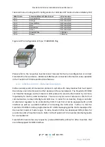
Table 4.2 Colour Coding and Pin Configuration for CAN Bus UTP Control Cable on Battery End
RJ45 Pin No.
Standard Ethernet Cable Colours
Wire Function
Pin 1
Orange/White
Not connected
Pin 2
Orange
Not connected
Pin 3
Green/White
Not connected
Pin 4
Blue
Not connected
Pin 5
Blue/White
Not connected
Pin 6
Green
Not connected
Pin 7
Brown/White
CAN High
Pin 8
Brown
CAN Low
Figure 4.2 Pin Configuration of Type T-568B RJ45 Plug
Please refer to the respective inverter brand manuals for their pin configuration or contact
Freedom Won for assistance. Additional CAN Bus pin connection information is also available
in the Freedom LiTE Home and Business Manual.
4.3.1.
CAN Bus Control
–
Detailed Description
CAN is a widely used communication protocol in systems with many devices that must report
their status or send commands to other devices on the same network. The Freedom LiTE BMS
can transmit messages and commands in CAN protocol to provide information to, but more
importantly to control, external devices. There are only two wires required in this form of
communication, namely CAN High and CAN Low. In order for an inverter, charge controller
or alternator regulator to be controlled by CAN it must first of all be equipped with a CAN
interface as well as a suitable method of connecting the CAN wires. Further to this the
Freedom LiTE BMS must be programmed with a CAN messaging profile that is developed for
the inverter model or model range. To date, Freedom Won has developed CAN profiles for
an extensive list of inverter brands. Refer to the Freedom LiTE to Inverter Interfacing Guide
for a complete list.
Freedom Won welcomes any request to produce BMS CAN profiles for other inverters that
are CAN equipped for BMS interface.


