VEHICLE SAFETY CONTROLLER
© 2021, FORT Robotics. Company Confidential. Do not distribute.
935-0003 Rev C
15 of 33
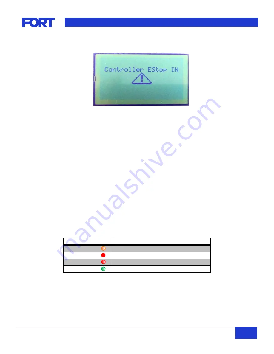
Figure 13: SRC Emergency Stop Display
The Master Enables will be de-asserted upon the following conditions:
1) The Emergency Stop Button on the SRC is activated.
2) The External Emergency Stop Input on the VSC is activated.
3) The Emergency Stop Software Input on the VSC is activated.
4) The VSC loses its connection to the SRC.
If the VSC has Master Enable indication asserted, this is considered an unsafe operating condition. It will
continue to output the heartbeat message with an indication that the Emergency Stop is active because of
the unsafe condition but will return to local mode or searching mode as specified. The VSC will also
continue to output the joystick message with all values set to 0 to guarantee no motion will occur. The
Master Enable outputs from the VSC will also be de-asserted and should be used to prevent motion.
The Master Enable outputs will only be asserted once the unsafe condition has been acknowledged and
corrected. The system will always revert to Local Mode after an E-Stop condition has occurred.
6.7.
VSC LED
The VSC LED indicator is tied to the state of the master enable of the VSC and the connection state of the
paired device to the VSC.
LED State
SRCS State
Blinking Amber
VSC in bootloader mode
Solid Red
Paired device is not connected or is in estop mode
Blinking Red
Paired device is connected and VSC estop enabled
Blinking Green
Paired device is connected and no estops enabled
Table 14: VSC LED States


