


VEHICLE SAFETY CONTROLLER
© 2021, FORT Robotics. Company Confidential. Do not distribute.
935-0003 Rev C
5 of 33
4.4.
Data Interfaces
The VSC’s
integration interface is USB, RS232, or CAN. The communication specifications (data rates and
protocol) are described in the system user manual. The dual Master Enable outputs should be used to
prevent any motion of the system under control when the VSC receives an emergency stop from either the
connected remote device or its wired emergency stop input. The emergency stop inputs are relative to
the PVin. A single ground reference should be maintained for all power and reverence voltages.
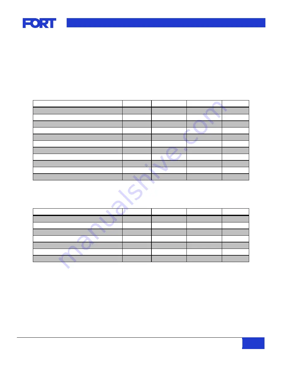
Parameter
Minimum
Typical
Maximum
Unit
CAN H/L Voltage
-2
7
V
CAN H/L baud rate
40
250
1000
kbps
CAN H/L high level input voltage
2
V
CAN H/L low level input voltage
0.8
V
CAN H/L high level output current - driver
-40
mA
CAN H/L high level output current - receiver
-8
mA
CAN H/L low level output current - driver
48
mA
CAN H/L low level output current - receiver
8
mA
CAN H/L positive going input threshold
750
900
mV
CAN H/L negative going input threshold
500
650
mV
CAN H/L input resistance
25
35
50
kΩ
Table 6 - CAN Interface Specifications
Note: CANbus installations require proper termination on the data lines (CAN_H & CAN_L) to ensure reliable
operation. Termination is not included in the VSC
Parameter
Minimum
Typical
Maximum
Unit
RS232 TX high level output voltage
5
5.4
V
RS232 TX low level output voltage
-5
-5.4
V
RS232 RX high level output voltage
5
5.4
V
RS232 RX positive going input threshold
1.5
2.4
V
RS232 RX negative going input threshold
0.6
1.2
V
RS232 RX input resistance
3
5
8
k
Ω
RS232 baud rate
115200
bps
Table 7
–
RS232 Interface Specification
4.5.
I/O Connector Pinout
The 19-pin I/O connector is where the majority of the system integration is done. Most applications will
only need this connector, leaving 6-pin USB connector capped.