


25
Handler I, II & III Operator’s Manual - October 2008
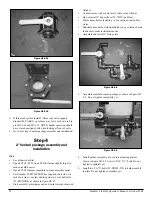
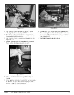
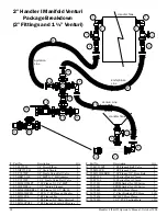
Venturi Nozzle Placement
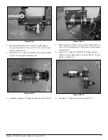
Figure H3-4.19
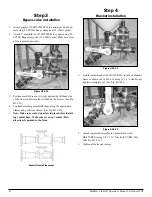
Install partial assembly on to venturi mounting plate as
shown in figure H3-4.19. Use two 3/8” X 1” bolts. Do not
tighten completely yet.
Install two 4” U-bolts (67-UB038-400) to hold assembly to
plate. Do not tighten completely yet.
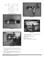
Figure H3-4.20
2.
3.
Figure H3-4.21
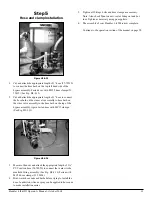
Assemble remaining 3” fittings as shown in figure H3-4.20
.
Mount second assembly to first as shown in figure H3-4.21
(use 25-FC300 clamp and 25-300G gasket). Do not tighten
completely yet.
Install 4 “ U-bolts (67-UB038-400) to hold second assembly
to intake support plate. See figure H3-4.21 . Do not tighten
completely yet.
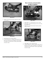
Figure H3-4.22
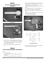
Assemble 1” fittings as shown in figure H3-4.22.
4.
5.
6.
7.
Содержание Handler I
Страница 2: ......
Страница 48: ...48 Handler I II III Operator s Manual October 2008...