


20
Handler I, II & III Operator’s Manual - October 2008
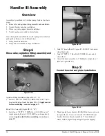
Handler III Assembly
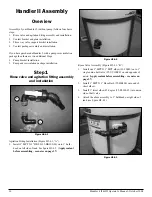
Overview
Assembly of your Handler 3 (without pump) follows four basic
steps:
Rinse valve and agitation fitting assembly and installation.
Venturi bracket and plate installation.
Three way valve support bracket installation.
Venturi package assembly and installation.
If you have purchased a Handler 3 with a pump or recirculation
package then there are two additional steps:
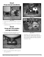
Pump bracket installation.
Pump and recirculation package installation.
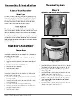
Step 1
Rinse valve/agitation fitting assembly and
installation
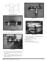
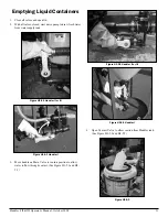
Figure H3-4.1
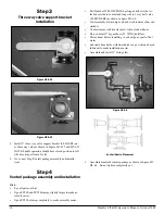
Agitation Fitting Installation (figure H3-4.1, “A”).
Install 1” MPT X 1” HB 90 (25-HB100-90) on to 1” bulk-
head on left side of tank. See figure H3-4.2.
(Apply sealant
before assembling - see notes on page 37)
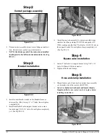
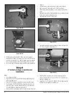
Rinse Valve Assembly (figure H3-4.1, “B”)
Install one 1” MPT X 1” MPT elbow (10-10980) on to 1”
single union ball valve (25-UV100FP) on end opposite of
union.
(Apply sealant before assembling - see notes on
page 37)
1.
2.
3.
4.
1.
2.
1.
1.
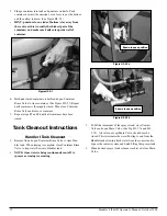
Figure H3-4.3
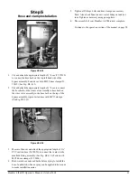
Install 1” street elbow 45 degree (25-SL100-45) into union
side of ball valve.
Install 1” MPT X 1” Hose Barb (25-HB100) onto end of
street elbow.
Attach the above assembly to 1” bulkhead on right side of
tank (see figure H3-4.3).
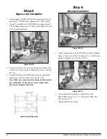
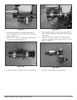
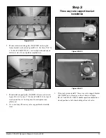
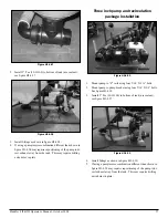
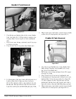
Step 2
Venturi bracket and plate installation
Figure H3-4.4
Mount angled frame brackets (86-HAFB) to frame as shown
in figure H3-4.4. Use two 1” U-bolts (67-UB025-100) per
bracket. Bottom of bracket should be 7” from bottom of
frame. NOTE: Tighten only enough to prevent slipping.
2.
3.
4.
1.
A
B
Содержание Handler I
Страница 2: ......
Страница 48: ...48 Handler I II III Operator s Manual October 2008...