


24
Handler I, II & III Operator’s Manual - October 2008
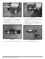
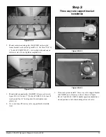
Figure H3-4.15
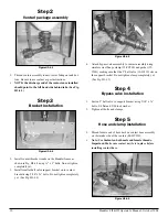
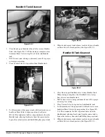
Install 2” bypass hose (54-79250) and secure with two
clamps (53-75632) per end as in figure H3-4.15.
Hint: Install hose at bottom end and ensure proper length.
Heat other end and install hose barb. Attach hose barb to
assembly.
Measure, cut and install 1” clear braided hose (54-79210)
for agitation and jug rinse lines. Secure with clamps (53-
75612).
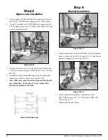
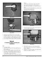
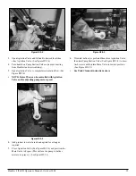
Figure H3-4.16
Install 2”FPT X 1 ½” hose barb 90 degree fitting on to bot-
tom of tank, see figure H3-4.16
13.
14.
15.
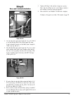
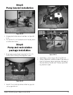
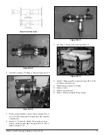
Figure H3-4.17
Measure, cut, and install 1 ½” PVC suction hose (54-79050)
that goes between tank and venturi valve. Secure with
clamps (53-75624). See figure H3-4.17
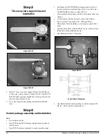
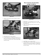
3” Venturi package assembly and
installation
Hints: see hints in 2” venturi package assembly and installation
instructions.
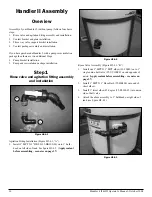
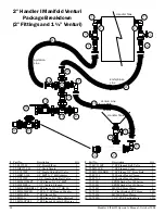
Figure H3-4.18
Assemble manifold venturi package as shown in figure H3-
4.18. Do not tighten completely yet.
16.
1.
Содержание Handler I
Страница 2: ......
Страница 48: ...48 Handler I II III Operator s Manual October 2008...