


22
Handler I, II & III Operator’s Manual - October 2008
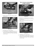
Figure H3-4.34
Figure H3-4.35
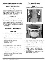
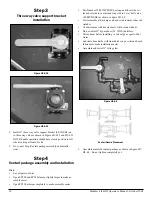
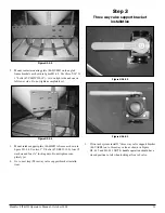
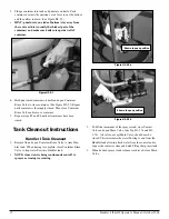
If three inch system install 3” three way valve support
bracket (86-VASB3) on to three way valve as shown in Fig-
ures H3-4.34 and H3-4.35 NOTE: handle operation should
have closed position to left when looking at front of valve.
Go to next step (Venturi package assembly and installation).
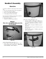
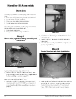
Step 4
2” Venturi package assembly and
installation
Hints:
Lay all parts out first.
Open FC200 , FC220 and FC300 clamps slightly larger to
make assembly easier.
Open FC100 clamps completely to make assembly easier.
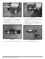
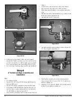
Part Number 25-M220CPG90 has long and short side. At-
tach short side to venturi and long side to 3 way ball valve
(25-MV220BL) as shown in figure H3-4.7
Start assembly at discharge end and work towards other end
2.
3.
•
•
•
•
•
(intake).
Venturi comes with nozzle insert, will not run without.
Do not install 2” bypass hose (54-79250) until last.
Warm hoses before installing – use heat gun or pail of hot
water.
Lubricate hose barbs with liquid dish soap or silicone based
lubricant to make installation easier.
Assemble and install 1” fittings last.
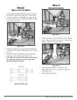
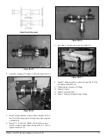
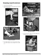
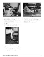
Figure H3-4.8
Assemble manifold venturi package as shown in figure H3-
4.8. Do not tighten completely yet.
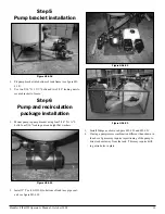
Figure H3-4.9
Install partial assembly on to venturi mounting plate as
shown in figure H3-4.9. Use two 5/16” X 1” bolts. Do not
tighten completely yet.
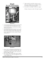
Install two 2 ½” U-bolts (67-UB038-250) to hold assembly
to plate. Do not tighten completely yet.
•
•
•
•
•
1.
2.
3.
Содержание Handler I
Страница 2: ......
Страница 48: ...48 Handler I II III Operator s Manual October 2008...