


13
Handler I, II & III Operator’s Manual - October 2008
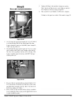
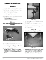
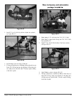
Step 5
Hose and clamp installation
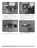
Figure H1-4.13
Cut and attach the appropriate length of 1” hose (57-79210)
to connect the hose barb on the top left hand side of the
bypass assembly. Fasten hose with MC12 hose clamps (53-
75612) (See Fig. H1-4.13)
Cut and attach the appropriate length of 1” hose to connect
the hose barb on the rinse valve assembly to hose barb on
the rinse valve assembly to the hose barb on the top of the
bypass assembly. Again fasten hose with MC12 clamps.
(See Fig. H1-4.13)
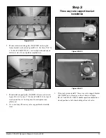
Figure H1-4.14
Measure, then cut and attach the appropriate length of 1 ½”
PVC suction hose (54-79050) to connect the venturi to the
manifold fitting assembly. (See Fig. H1-4.14) Fasten with
MC24 hose clamps (53-75624).
Hint: warm hose ends and barbs before trying to install the
hose. In addition, silicone spray can be applied to hose ends
to make installation easier.
1.
2.
3.
4.
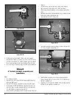
Tighten all fittings, bolts and hose clamps as necessary.
Note: Also check flynut on anti-vortex fitting on tank bot-
tom. Tighten as necessary using pump pliers.
The assembly of your Handler 1-i15M is now complete.
Continue to the operation section of the manual on page 28.
5.
6.
Содержание Handler I
Страница 2: ......
Страница 48: ...48 Handler I II III Operator s Manual October 2008...