FMC Ao4 Скачать руководство пользователя страница 12

Doc No: OMM50001254 

Rev:  A  Page 12 of 47 

Subject to contractual terms and conditions to the contrary, this document and all the information contained herein are the confidential and exclusive  

property of FMC Technologies, and may not be reproduced, disclosed, or made public in any manner prior to express written authorization by FMC. 

The suction line must be configured so there are no high spots in the line where air 
pockets can collect.  These pockets may make the pump difficult to prime and cause 
rough, erratic operation. A drain valve or plug should be installed at the low point of the 
suction line to allow for draining before freezing conditions or for maintenance. 

FMC recommends that all piping be supported independently of the pump.  By 
supporting the piping this way, vibrations are reduced and stress on the pump is kept to 
a minimum.  The use of elbows, nipples, unions, or other fittings should be minimized.  
Make sure that all joints and connections are airtight.  Air leaks reduce the capacity of 
the pump and can result in cavitation, rough operation, and/or loss of prime.  To help 
isolate mechanical and hydraulic vibrations, FMC recommends the use of flexible pipe 
couplings or hose connections between the pump and any rigid piping. 

Always ensure that calculated system Net Positive Suction Head available, NPSHa, 
exceeds pump Net Positive Suction Head required, NPSHr, by at least 5 feet (1.5 
meters) of water for proper operation of the pump.  NPSH requirements for each pump 
model are provided on the product data sheets available through FMC or your 
authorized FMC reseller.  FMC does not recommend using the pump in static lift 
conditions without prior factory approval. 

3.4 

Discharge Piping Recommendations 


1.  Route the discharge piping in as short and direct a route as possible.  Use the 

same pipe size as the outlet of the pump.  In installations where the discharge 
piping is in excess of 50 feet (15 meters) it is suggested to use the next larger 
size pipe to minimize friction losses downstream of the pump. 


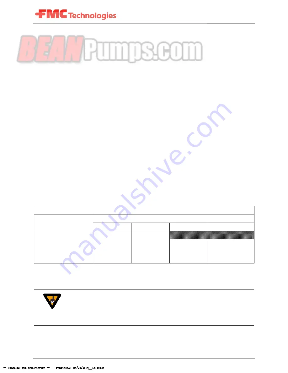
Table 1: MAWP for Steel Pipe 

Allowable Working Pressure For Steel Pipe (PSI @ 100F) 

Pipe Schedule Number 

Pipe Size (inches) 

40 

80 

160 

XX 

 3/8 

1,700 

3,800 


 1/2 

2,300 

4,100 

7,300 

12,300 

 3/4 

2,000 

3,500 

8,500 

10,000 

1     

2,100 

3,500 

5,700 

9,500 


14.5 psi = 1 Bar 


CAUTION 

Always use pipe or hose that is designed for your particular pressure requirements.  
Inadequate pressure ratings can allow hose or pipe to fail, resulting in equipment damage 
and possibly personal injury.  Normal hose pressure ratings are clearly marked on the 
outer surface of the hose.  Working pressure ratings for steel pipe can be obtained from 
the manufacturer or from the chart shown tin Table 1. 


Содержание Ao4

Страница 1: ...nner prior to express written authorization by FMC OPERATION AND MAINTENANCE MANUAL A04 I04 PUMP ASSEMBLIES Rev ECN No Date Reviewed By Approved By Status A 5021211 23 APR 2009 Taylor Justin Singleterry Ronald RELEASED Summary This is a manual for FMC A04 and I04 duplex piston pumps These pumps are direct drive no pinion shaft and have a stroke length of 1 00 The continuous power rating is 2 6 hp ...

Страница 2: ...rning a Stored Pump to Operation 9 2 4 Precautions during Freezing Weather 9 3 0 Installation Guidelines 10 3 1 General Location 10 3 2 Mounting Pump to Foundation and Power Source 10 3 2 1 A04 Pump Mounting Guideline 11 3 2 2 I04 Pump Mounting Guideline 11 3 3 Suction Piping Recommendations 11 3 4 Discharge Piping Recommendations 12 3 5 Multiple Pump Systems 13 4 0 How to Start a Pump 14 5 0 Lubr...

Страница 3: ...roduced disclosed or made public in any manner prior to express written authorization by FMC 9 0 Service Procedures 25 9 1 Replacing Cup Pistons 26 9 2 Replacing Suction and Discharge Valves 30 9 3 Servicing the Power End 33 10 0 Fastener Torque Requirements 37 11 0 Critical Clearances 38 12 0 Trouble Shooting Pumps 39 13 0 Ordering Parts 42 14 0 Glossary of Commonly Used Terms 43 15 0 Reference I...

Страница 4: ... and exclusive property of FMC Technologies and may not be reproduced disclosed or made public in any manner prior to express written authorization by FMC List of Tables Tables Page Table 1 MAWP for Steel Pipe 12 Table 2 Recommended Lubricant Chart 17 Table 3 Maintenance Chart 18 Table 4 Component Parts List 24 Table 5 Torque Requirements 37 Table 6 Critical Clearances 38 ...

Страница 5: ...tial and exclusive property of FMC Technologies and may not be reproduced disclosed or made public in any manner prior to express written authorization by FMC List of Figures Figures Page Figure 1 A04 Pump Features 7 Figure 2 I04 Pump Features 8 Figure 3 A04 I04 Fluid End 21 Figure 4 A04 Power End 22 Figure 5 I04 Power End 23 Figure 6 Valve Seat Removal Tool 1250638 32 ...

Страница 6: ...UT A PRESSURE RELIEF VALVE rupture disc or other type of properly sized over pressure safety device installed ALWAYS USE A PRESSURE GAGE when operating the pump The pressure must never exceed the maximum pressure rating of the pump or damage may occur This damage can cause leakage or structural damage resulting in injury to personnel ENSURE THAT NO VALVES ARE PLACED BETWEEN THE PUMP AND PRESSURE R...

Страница 7: ...es you ll find built into every FMC pump Figure 1 A04 Pump Features Corrosion resistant disc valves are stacked in the fluid end using o ring seals for easy service Wide variety of piston cup designs to suit the needs of any application Hardened steel wrist pins are ground to a mirror finish for a precise fit Aluminum alloy connecting rods have wrist pin bushings and split insert bearings Spring l...

Страница 8: ...ersion of the A04 pump Virtually all of the same options are available for either pump Durable cast iron power frame Heavy duty oversized ball bearings Spring loaded oil seals keep oil inside and contaminants out Choice of 7 8 straight keyed or 13 tooth splined shaft with SAE 2 bolt configurations High strength Aluminum alloy connecting rod Polished ceramic liners provide unsurpassed wear and corr...

Страница 9: ...ssed air used to blow dry whenever idle 2 2 Short Term Storage for Severe Environments If the pump has been in service drain any fluid from pump fluid end flush the fluid end with water to clean out any of the remaining pumpage and blow dry with compressed air Pour 1 4 cup of internal rust inhibitor oil described in Table 2 into the suction and discharge ports of fluid end and then install pipe pl...

Страница 10: ...through the fluid end RV antifreeze propylene glycol is recommended for this purpose Remember that any fluid that poses an environmental hazard or is toxic must be handled and disposed of properly 3 0 Installation Guidelines A proper installation is essential to optimal performance long service life and reduced maintenance requirements Take time to thoroughly plan all aspects of your installation ...

Страница 11: ...en in operation 3 3 Suction Piping Recommendations Poor suction piping practices are a very common source of pump problems To ensure proper operation it is very important to follow good design practice in the installation of the suction system before the pump is operated A small amount of additional planning and investment in the piping system usually provides for better pump performance and longe...

Страница 12: ... piping Always ensure that calculated system Net Positive Suction Head available NPSHa exceeds pump Net Positive Suction Head required NPSHr by at least 5 feet 1 5 meters of water for proper operation of the pump NPSH requirements for each pump model are provided on the product data sheets available through FMC or your authorized FMC reseller FMC does not recommend using the pump in static lift co...

Страница 13: ...stead To help isolate mechanical and hydraulic vibrations FMC recommends the use of flexible pipe couplings or hose connections between the pump and any rigid piping The use of pulsation dampeners can also reduce hydraulic pulsation and resultant vibrations 4 A properly adjusted pressure relief valve or rupture disc must be installed directly downstream of the pump to prevent damage or injuries re...

Страница 14: ... level to ensure that the pump is properly filled with non detergent motor oil gear lube or a synthetic oil as described in Table 2 and that the oil has not been contaminated with water or other contaminants NOTE FMC pumps are shipped with no oil in the power frame and must be filled to the proper level with the proper grade of oil prior to start up Pump model A04 requires 1 quart 0 95 liters of o...

Страница 15: ... unobstructed operation 7 Make sure that all guards are in place and secure Verify that all personnel are in safe positions and that system conditions are acceptable for operation 8 The pump is now ready to start NOTICE Whenever possible use a bypass in the discharge line to allow the pump to start in the unloaded condition no discharge and pressure Slowly close the bypass line to bring the pump i...

Страница 16: ...r Consult FMC for lubrication recommendations for applications that fall outside of the conditions listed in Table 2 NOTE Lubricant temperatures should not exceed 170 F 77 C for continuous duty or 180 F 82 C for intermittent duty applications Crankc ase temperatures that exceed these limits will cause the lubricant to prematurely break down The result will be poor lubrication and failure of power ...

Страница 17: ...NA 90 0 40 15 0 100 99 1 40 13 9 100 Shell Rotella T Synthetic SAE 5W 40 Mobil SCH 627 High Ambient Temperature Service 100 F to 130 F 38 C to 54 C 50 250 1165 Texaco Meropa 68 Shell Omala 220 Shell Rotella T SAE 50 Exxon HD 3 50 wt Mobil Trans HD 50 5W 40 NA 90 0 40 15 0 100 217 40 29 9 100 Shell Rotella T Synthetic SAE 5W 40 Mobil SCH 630 Cold Ambient Temperature Service 0 F to 30 F 18 C to 34 C...

Страница 18: ...tions will require adjustment of the intervals shown in this chart for severe or unusual operating conditions Table 3 Maintenance Chart Interval Component Service Remarks Break In Crankcase Oil Change Drain and refill with new oil after first 50 hours of operation Ensure that the magnetic drain plugs are cleaned to remove debris Period Inlet Strainer Inspect Clean if Required The amount of materia...

Страница 19: ...o facilitate maintenance schedules and stocking of spares The maintenance of the power end lubrication system will influence the life of the power end components The speed of operation and percent of maximum allowable load will influence the life of both power end and fluid end parts The temperature abrasiveness and lubricity of the liquid affect the life of fluid end expendables POWER END COMPONE...

Страница 20: ...es This will aid in identifying components for service procedures outlined in the following sections To order service parts or see exact component configurations for your particular pump contact your local FMC pump distributor or FMC if you do not have this information The A04 power end assembly Figure 4 is shown with a hydraulic drive spine shaft connection and the I04 power end assembly Figure 5...

Страница 21: ...e contrary this document and all the information contained herein are the confidential and exclusive property of FMC Technologies and may not be reproduced disclosed or made public in any manner prior to express written authorization by FMC 8 1 A04 I04 Fluid End Figure 3 A04 I04 Fluid End ...

Страница 22: ...trary this document and all the information contained herein are the confidential and exclusive property of FMC Technologies and may not be reproduced disclosed or made public in any manner prior to express written authorization by FMC 8 2 A04 Power End Vertically Mounted Figure 4 A04 Power End ...

Страница 23: ...rary this document and all the information contained herein are the confidential and exclusive property of FMC Technologies and may not be reproduced disclosed or made public in any manner prior to express written authorization by FMC 8 3 I04 Power End Horizontally Mounted Figure 5 I04 Power End ...

Страница 24: ... 20 Self Tapping Screw 2 2 21 Lube Vent 1 1 22 Key 1 1 23 Front Foot N A 1 24 Lock Washer Front Foot N A 2 25 Oil Slinger 1 N A 26 Bolting Strip Oil Slinger 1 N A 27 Cap Screw Oil Slinger 2 N A 28 Hex Nut Oil Slinger 2 N A 29 Retainer Ring 1 1 30 Spline Adapter 1 1 31 Protective Cover 1 1 32 Lock Washer 2 2 33 Cap Screw Connection Flange 2 2 34 Nipple Lube Vent 1 N A 35 Elbow Lube Vent 1 N A 36 Ni...

Страница 25: ... A04 pump assembly The procedures are also applicable to the I04 assembly The main difference is that the A04 is a vertically positioned pump and the I04 is a horizontally positioned pump The service procedures outlined in this manual are intended to describe the more popular type of pump Other configurations and minor design differences may exist with alternate pumps Some procedures may require s...

Страница 26: ...the fluid cylinder 38 from pump by removing the three cap screws 39 holding it to the power frame then lift the fluid cylinder off the top of the ceramic cylinders 42 3 Remove the ring seals 41 and o rings 40 from the top of the cylinders or from the counter bores of the fluid cylinder 4 Remove the cap screw 44 and piston cup washer 45 from each of the two cylinders 5 Lift the ceramic cylinder 42 ...

Страница 27: ...ores Note to provide maximum operational time between service FMC recommends that both piston cups not just the one that shows signs of leakage be replaced whenever piston service is required 8 Ensure that the umbrella fluid shield 50 is not damaged A damaged umbrella could allow fluid to contaminate the power end oil If the umbrella requires replacement the best way to remove it from the pump is ...

Страница 28: ...facing up Press top of umbrella down to seat it over the umbrella washer and crosshead shaft Note I04 pumps are not equipped with umbrellas 11 Place o rings 48 and piston holders 47 in position on ends of crosshead shaft 12 Place ceramic cylinders 42 and gaskets 43 in counterbore of power frame 1 13 Apply light oil or glycerin around the OD of the piston cups 46 then place them in the open end of ...

Страница 29: ...ed disclosed or made public in any manner prior to express written authorization by FMC 16 Insert top o ring 40 and ring seal 41 in fluid cylinder counterbore using heavy oil or grease to hold in place 17 Return fluid cylinder 38 to position over cylinders 42 and ensure that all seals are in place 18 Replace fluid end cap screws 39 Torque cap screws in 3 stages to values shown in the Fastener Torq...

Страница 30: ...ed or made public in any manner prior to express written authorization by FMC 9 2 Replacing Suction and Discharge Valves 1 Remove cap screw 58 and valve cover clamp 57 from the front of the fluid cylinder 38 2 Insert the end of a standard screwdriver into the valve cover 56 groove and pry the valve cover away from the fluid cylinder 38 3 Remove the valve cage 55 and discharge valve disc spring ass...

Страница 31: ...alve seat 6 Inspect all valve components and replace as necessary Note that even small damage or erosion to the sealing area of the valve or the o ring can adversely affect the performance of the pump 7 With the o ring 52 in place on each valve seat 51 place a few drops of light oil around the o ring to aid in installation Place a valve seat SQUARELY in the back of both counter bores of the fluid ...

Страница 32: ...o the contrary this document and all the information contained herein are the confidential and exclusive property of FMC Technologies and may not be reproduced disclosed or made public in any manner prior to express written authorization by FMC Figure 6 Valve Seat Removal Tool 1250638 ...

Страница 33: ...rvice work Ensure the power to the pump is off and disconnected If applicable it should be locked and tagged out 1 Remove bottom drain pipe plug 17 and drain all oil from power frame 2 Disconnect suction and discharge piping power source and remove pump from mounting base 3 Although it is not required it is easier to remove the crankshaft 2 if the fluid end and pistons have been removed To remove ...

Страница 34: ...connecting rod shell bearing 4 NOTE Connecting rod halves are not interchangeable and must be reassembled in their original positions Note the orientation of the machine markings on the connecting rod and cap 6 Remove the oil slinger 25 from the crankshaft 2 A04 model only 7 Push the connecting rods 3 and crosshead assemblies 6 as far forward into the power frame as possible to provide clearance f...

Страница 35: ...e suitable support for the back side of the bearings during this step Note Never pound directly on the bearings or they may be damaged 12 Once the crankshaft has been removed the connecting rods and crossheads can be pulled from the back of the power frame opening 13 The wrist pin 5 is a slip fit through the connecting rod 3 and crosshead 6 Check for signs of wear on the pin and connecting rod bus...

Страница 36: ... of the seals facing the inside of the power frame 20 Seat the snap rings 13 in the grooves in the bearing housing against the oil seals and tap the crankshaft to allow a SLIGHT endplay in the crankshaft 21 Reassemble the connecting rods and shell bearings around the crankshaft The connecting rod and cap are a matched set Be sure to properly match the connecting rods and caps back into their origi...

Страница 37: ...that the fasteners have been properly torqued Failure to properly tighten the pump bolts could cause the pump to leak or possibly allow the pump to fail Always use a calibrated torque wrench during the installation of all critical fasteners listed in Table 5 below Values are in foot pounds Ft lb and Newton meters N m Typical sizes are shown in Table 5 Table 5 Torque Requirements Item Component A04...

Страница 38: ...ance is allowed for component wear This additional clearance is a maximum of 002 inches of total diametral wear that can be added to the clearance values in Table 6 For radial clearance use of the total diametral value All dimensions are shown in Inches Table 6 Critical Clearances DESCRIPTION A04 I04 Crankshaft Throw Diameter Stroke 1 00 Crankshaft Pin or Journal OD 8725 8715 Connecting Rod Crank ...

Страница 39: ...r power to motor Check relief valve and adjust setting Properly service system Inspect check valves and repair or replace Adjust or replace packing or damaged parts Insufficient flow from pump ONLY Pump speed is too low Relief valve improperly adjusted or worn Worn pump valves Excessive leakage from pump seals Piston worn Valve seat washed out in fluid cylinder Check belt tightness or power to mot...

Страница 40: ...on to stop leaks Piping vibration Same as Pump runs rough above Excessive pressure variation in discharge Piping inadequately supported Excessive short radius elbows or tees See above Install discharge pulsation dampener Install supports at proper locations Correct installation to minimize turns and short radius fittings Pump requires excessive power Discharge pressure too high Speed too high Misa...

Страница 41: ...stall strainer or filter Correct problem and replace damaged valves Correct problem Increase submergence or baffle to stop vortex Pipe back to reservoir tank Replace damaged components Cracked fluid cylinder or broken fluid end bolts Discharge pressure too high Hydraulic shock cavitation or entrained air Discharge valve stuck closed Fluid freezing in fluid cylinder Material or manufacturing defect...

Страница 42: ... for the location of an authorized parts retailer in your area Always insist on genuine FMC replacement parts Use the assembly drawing and bill of material included with this manual to determine the components and corresponding part numbers required to service the pump Make sure that the part number on the drawing or bill of material matches the part number of the pump requiring parts When orderin...

Страница 43: ...tion and discharge valves during the suction stroke and often sounds like a mechanical knock Cavitation results in the formation of gas bubbles or cavities in the fluid that cause vibration and damage to components when they collapse DAMPENER A device that reduces pressure pulsations in the suction or discharge piping This may be referred to as a suction stabilizer accumulator or surge suppressor ...

Страница 44: ...mping temperature NPSHA for a reciprocating pump is normally expressed in units of feet of water NPSHr An abbreviation that stands for Net Positive Suction Head Required This is the minimum total inlet pressure required by the pump for proper operation This value is a function of pump design and speed and is determined by the pump manufacturer through a specific NPSH test NPSHA should exceed NPSHR...

Страница 45: ...d herein are the confidential and exclusive property of FMC Technologies and may not be reproduced disclosed or made public in any manner prior to express written authorization by FMC PUMP VALVE A check valve that allows flow of liquid in one direction FMC pumps have a series of two valves one suction inlet and one discharge per pumping cylinder ...

Страница 46: ...formation such as part and serial numbers will be needed when ordering service parts This data may be found stamped on the metal nameplate located on the pump power frame This area may also be used to make notations about special parts procedures phone numbers or other important information related to your pump Pump Model ________________________________________ Part Number _______________________...

Страница 47: ...ary this document and all the information contained herein are the confidential and exclusive property of FMC Technologies and may not be reproduced disclosed or made public in any manner prior to express written authorization by FMC 16 0 MAINTENANCE LOG DATE SERVICED BY SERVICE PERFORMED REMARKS ...

Отзывы: