background image


TECHNICAL DOCUMENTATION: 


EN 


1.


IMPORTANT INFORMATION 

We have made every effort to make this manual as easy to understand as possible. However, if you have any difficulties, problems or 
questions, please contact FLOWAIR support at: [email protected] 
Also visit our website www.flowair.pl where you will find mounting tips. 
In this manual you will find important safety information and tips marked as below: 
 

WARNING


Dangerous practices which may 
result in serious injury or death. 
Read all warnings before starting 
work.


CAUTION


unsafe practices which, if not 
avoided, may result in damage to 
property or minor injuries. 
Before starting work, read all 
cautions. 


ADVICE


Useful tips for the user and 
installer.


IMPORTANT SAFETY INFORMATION: 
 

ADVICE


1. Before installing, connecting, starting up, using and maintaining the device, please read this manual completely. 
2. After receiving the product, check that it has not been damaged during transport. If the product appears to be 
damaged, DO NOT START TO MOUNT THE DEVICE; instead, you must immediately report the damage to the 
carrier. 
3. The device must be mounted in a stable way and in accordance with the instructions, in a place that can be 
easily accessed, thus ensuring the possibility of carrying out repairs and routine maintenance, as well as allowing 
easy and safe disassembly of the device. 
4. The stability and durability of installation of the device depends on the structure of the building (in particular 
walls and ceilings). The person performing the assembly should take these conditions into account when mounting 
the device. 
5. The technical documentation should be kept in a safe place, easily accessible to the user and service technician. 
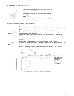
6. The nameplate is located next the cable glands on the top of the device. 
7. Always test the operation of the device after installation. 
8. The device should not be installed directly under the wall socket 
 

CAUTION


1. The power connection shall be performed only by an authorized person. 
2. The device may start automatically (when motion is detected in the sensor area). 
3. The device is not equipped with a thermostat that controls the room temperature. Do not use the device in 
small rooms where there are people who are not able to leave the premises alone. Above mentioned does not 
apply to rooms with constant supervision. 
4. The device requires periodic inspections in accordance with the instructions in this manual. 
5. Do not hang/put pressure on the device. 
6. Do not place any objects on the device or hang anything on the connection stubs. 
7. The product should be stored and assembled out of the reach of small children. 
8. The device is dedicated to work indoors with a maximum air dustiness of 0.3 g / m3. The device has elements 
made of aluminum, copper and galvanized steel and cannot be used in an corrosive environment. 
9. Equipment cannot be used in an environment where oil mist is present. 
10. This equipment may be used by children that are  at least 8 years old, by persons with reduced physical and 
mental abilities and persons with no experience and knowledge of the equipment, on condition that the 
supervision or instruction regarding correct use of the equipment in a safe manner is provided and the possible 
threats are understood. The device cannot be used by children to play. Unattended children should not clean or 
maintain the equipment. 
11. The device in electric version (SLIM E) may give off a smell of burning dust at first start up  or if it is starting 
after a long standstill.  
 

WARNING


1. The device is powered by dangerous voltage. Always disconnect the device from the power supply before 
servicing or accessing its internal components. 
2. Do not insert your fingers or any objects inside the device. 
3. Do not cover the device. 


Содержание ELIS G E-150

Страница 1: ...1 PL KURTYNA POWIETRZNA DOKUMENTACJA TECHNICZNA ELIS G E 150 E 200 E 250 W 150 W 200 W 250 N 150 N 200 N 250 W 150 2R W 200 2R EN AIR CURTAIN DOKUMENTACJA TECHNICZNA ...

Страница 2: ...EANING AND MAINTENANCE 16 21 COMPLIANCE WITH WEEE 2009 19 EC 16 22 DECLARATION OF CONFORMITY 17 23 SERVICE AND WARRANTY TERMS 18 DOKUMENTACJA TECHNICZNA PL SPIS TREŚCI 1 WAŻNE INFORMACJE 19 2 INFORMACJE OGÓLNE 20 3 BUDOWA 20 4 DANE TECHNICZNE ELIS G W 21 5 DANE TECHNICZNE ELIS G N E 22 6 WYMIARY 23 7 MONTAŻ 23 8 MONTAŻ ZALECANE ODLEGŁOŚCI 24 9 PODŁĄCZENIE INSTALACJI ELEKTRYCZNEJ 25 10 STEROWANIE S...

Страница 3: ...ways test the operation of the device after installation 8 The device should not be installed directly under the wall socket CAUTION 1 The power connection shall be performed only by an authorized person 2 The device may start automatically when motion is detected in the sensor area 3 The device is not equipped with a thermostat that controls the room temperature Do not use the device in small roo...

Страница 4: ...aximum range 7 5 m ELIS G W 150 2R ELIS G W 200 2R ELIS G W 250 2R air curtains with a water heat exchanger with a maximum range 7 5 m ELIS G N 150 ELIS G N 200 ELIS G N 250 air curtains without water exchanger maximum range 8 0 m according to ISO 27327 1 inlet outlet PIC 2 1 DIRECTION OF AIR FLOW PIC 2 2 AIR STREAM RANGE FOR DIFFERENT FAN STEPS ADVICE 1 In buildings where thermal comfort is requi...

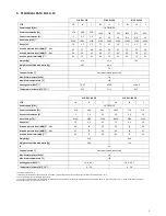
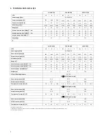
Страница 5: ...III II I III II I Power supply V Hz 1N 230 50 Power consumption W 670 480 240 1050 730 370 Current consumption A 3 2 3 1 3 4 5 3 6 1 9 Air volume m3 h 6100 3900 2400 8800 5400 3100 Range m 7 5 4 2 2 5 7 5 4 2 2 5 Acoustic pressure level dB A 3 m 68 58 47 70 59 48 Acoustic pressure level dB A 5 m 67 57 46 69 58 47 Acoustic power level dB A 83 73 62 85 74 63 Weight kg 51 8 66 4 Weight of unit filled...

Страница 6: ... h 6300 4300 2600 9400 5700 3400 12400 7800 4900 Range m 7 5 4 5 2 8 7 5 4 5 2 8 7 5 4 5 2 8 Acoustic pressure level dB A 3 m 66 56 45 67 57 46 69 59 47 Acoustic pressure level dB A 5 m 65 55 44 66 56 45 68 58 46 Acoustic power level dB A 81 71 60 82 72 61 84 74 62 Weight kg 47 62 2 77 9 IP fan IP heating elements 54 20 3N 400 50 3 power step Power consumption kW 13 5 20 5 24 5 Current consumption...

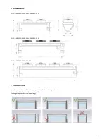
Страница 7: ...ELIS G N 200 G W 200 G W 200 2R G E 200 ELIS G N 250 G W 250 G E 250 7 INSTALATION Air curtains must be installed as close as possible to the door opening and cover the entire width applies to horizontal installation full height applies to vertical mounting ...

Страница 8: ... B mm N W E 150 585 1480 N W E 200 585 2000 N W E 250 585 2495 PIC 8 1 HORIZONTAL INSTALATION The maximum length of the set is 10 m In case of horizontal installation use installation plate and mount unit via threaded pins M10 not included Single unit is mounted on 4 installation plates two units on 6 pcs Installation plates are used to screw units among themselves as show on drawing PIC 8 2 VERTI...

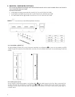
Страница 9: ...designer Always make sure that disconnectors and circuit breakers are properly sized and disconnect all poles of the power supply 3 Make sure that the connection of power supply and controllers to the ELIS G curtain is made in accordance with the electrical specifications and the instructions included in the connection diagrams in the technical documentation 4 Before connecting the power supply ch...

Страница 10: ...E 200 min 5x6 0 mm2 overcurrent B40 Control signal to junction box OMY min 2x0 5 mm2 glands PG29 PG9 FK1 FK2 FK3 overload protector 6 3 A ADVICE 1 To connect the cables from the RX to the curtain disassemble the cover of the fan box and then lead the cable through the free gland 2 Without a door sensor the air curtain will work in relation to the setting from TS thermostat When working with a door...

Страница 11: ... signal to junction box OMY min 2x0 5 mm2 glands PG29 PG9 FK1 FK2 FK3 overload protector 6 3 A ADVICE 1 To connect the cables from the RX to the curtain disassemble the cover of the fan box and then lead the cable through the free gland 2 Without a door sensor the air curtain will work in relation to the setting from TS thermostat When working with a door sensor the curtain will be activated only ...

Страница 12: ...tion of power supply for ELiS G curtain fans one connector can be connected to one curtain OMY min 5x1 0 mm2 glands PG7 PG9 SRQ SRQ3d valve power supply OMY min 3x0 75 mm2 FK1 FK2 FK3 overload protector 6 3 A ADVICE 1 To connect the cables from the RX to the curtain disassemble the cover of the fan box and then lead the cable through the free gland 2 Without a door sensor the air curtain will work...

Страница 13: ... 0 mm2 glands PG7 PG9 SRQ SRQ3d valve power supply OMY min 3x0 75 mm2 FK1 FK2 FK3 overload protector 6 3 A ADVICE 1 To connect the cables from the RX to the curtain disassemble the cover of the fan box and then lead the cable through the free gland 2 By default three fans are connected together the fourth one should be connected separately to another channel of the RX distributor 3 Without a door ...

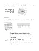
Страница 14: ...r running time 18 TS 3 step regulator with built in thermostat Temperature setting range 10 30 oC Operating temperature range 0 40 oC Protection degree IP30 Contact load inductive 5 A Supply voltage 230 V 50 Hz FAN AUTO fan operation depends on the temperature FAN CONT continuous fan operation HEAT heating function FAN deactivate the thermostat for FAN CONT COOL reversal of the operation logic of ...

Страница 15: ...nst the increase of the heating medium pressure above the permissible value 1 6 MPa 5 Before starting the device check the correct connection of the heating medium and the system for leaks 6 During assembly of the installation it is absolutely necessary to immobilize the exchanger s connector pipes counter 7 After filling the system with heating medium check the tightness of the hydraulic connecti...

Страница 16: ...e blown with compressed air 20 CLEANING AND MAINTENANCE ADVICE Periodically check at least twice a year the dirtiness level of the heat exchanger ELIS G W electric heaters ELIS G E Clogging a part of the air intake causes a decrease in the heating power of the device and adversely affects the operation of the fan and in the case of electric heaters it can cause permanent loss of rated parameters C...

Страница 17: ...ej were produced in accordance to the following Europeans Directives 1 2014 30 UE Kompatybilności elektromagnetycznej Electromagnetic Compatibility EMC 2 2006 42 WE Maszynowej Machinery 3 2014 35 UE Niskonapięciowe wyroby elektryczne Low Voltage Electrical Equipment LVD 4 2009 125 WE Produkty związane z energią Energy related products ErP 2015 oraz zharmonizowanymi z tymi dyrektywami normami and h...

Страница 18: ...e contact the manufacturer s service department The manufacturer bears no responsibility for operating the device in a manner inconsistent with its purpose by persons not authorised for this and for damage resulting from this Made in Poland Made in EU Manufacturer FLOWAIR GŁOGOWSKI I BRZEZIŃSKI SP J ul Chwaszczyńska 135 81 571 Gdynia tel 48 58 669 82 20 e mail info flowair pl www flowair com ...

Страница 19: ...acji należy zawsze przetestować działanie urządzenia 8 Urządzenia nie należy instalować bezpośrednio pod gniazdem wtyczkowym PRZESTROGA 1 Podłączenie zasilania powinna wykonać wyłącznie odpowiednio uprawniona osoba 2 Urządzenie może uruchomić się w sposób automatyczny po wykryciu ruchu w obszarze czujnika 3 Urządzenie nie jest wyposażone w termostat kontrolujący temperaturę w pomieszczeniu Nie uży...

Страница 20: ... m ELIS G W 150 2R ELIS G W 200 2R ELIS G W 250 2R kurtyny z wodnym wymiennikiem ciepła o maks zasięgu 7 5 m ELIS G N 150 ELIS G N 200 ELIS G N 250 kurtyny bez wymiennika wodnego maks zasięgu strumienia 8 0 m zgodnie z ISO 27327 1 wlot wylot RYS 2 1 KIERUNEK PRZEPŁYWU POWIETRZA RYS 2 2 ZASIĘG POWIETRZA NA POSZCZEGÓLNYCH BIEGACH PORADA 1 Dla obiektów gdzie wymagany jest komfort użytkownika zalecane...

Страница 21: ... III II I III II I Napięcie znamionowe V Hz 1N 230 50 Znamionowy pobór mocy W 670 480 240 1050 730 370 Znamionowy pobór prądu A 3 2 3 1 3 4 5 3 6 1 9 Wydajność m3 h 6100 3900 2400 8800 5400 3100 Zasięg m 7 5 4 2 2 5 7 5 4 2 2 5 Poziom ciśnienia akustycznego dB A 3 m 68 58 47 70 59 48 Poziom ciśnienia akustycznego dB A 5 m 67 57 46 69 58 47 Poziom mocy akustycznej dB A 83 73 62 85 74 63 Masa kg 51 ...

Страница 22: ...ć m3 h 6300 4300 2600 9400 5700 3400 12400 7800 4900 Zasięg m 7 5 4 5 2 8 7 5 4 5 2 8 7 5 4 5 2 8 Poziom ciśnienia akustycznego dB A 3 m 66 56 45 67 57 46 69 59 47 Poziom ciśnienia akustycznego dB A 5 m 65 55 44 66 56 45 68 58 46 Poziom mocy akustycznej dB A 81 71 60 82 72 61 84 74 62 Masa kg 47 62 2 77 9 IP wentylatora IP grzałek 54 20 3N 400 50 3 stopień mocy Znamionowy pobór mocy kW 13 5 20 5 2...

Страница 23: ... E 150 ELIS G N 200 G W 200 G W 200 2R G E 200 ELIS G N 250 G W 250 G E 250 7 MONTAŻ Kurtyny powietrzne muszą być zamontowane jak najbliżej otworu bramowego i pokrywać całą szerokość dotyczy montażu poziomego całą wysokość dotyczy montażu pionowego ...

Страница 24: ...N W E 250 585 2495 RYS 8 1 MONTAŻ PODSTROPOWY Maksymalna długość zestawu 10 m W przypadku montażu podstropowego należy przez otwory montażowe uchwytu przełożyć szpilki M10 4 szt dla jednego urządzenia 6 szt dla dwóch urządzeń itd a następnie zablokować podkładką z nakrętką Uchwyt montażowy pomiędzy dwiema kolejnymi kurtynami jest elementem łączącym urządzenia RYS 8 2 MONTAŻ PIONOWY ZA POMOCĄ WSPOR...

Страница 25: ...ki i wyłączniki ochronne są odpowiednio zwymiarowane oraz odłączają wszystkie bieguny zasilania 3 Należy upewnić się że podłączenie zasilania oraz sterowników do kurtyny ELIS G jest wykonane zgodnie ze specyfikacjami elektrycznymi i z instrukcjami ujętymi na schematach przyłączeń w dokumentacji technicznej 4 Przed podłączeniem zasilania należy sprawdzić czy napięcie w sieci jest zgodne z napięciem...

Страница 26: ...00 min 5x6 0 mm2 zabezpieczenie B40 Sygnał sterujący do szafki nabudowanej na kurtynie OMY min 2x0 5 mm2 dławnice PG29 PG9 FK1 FK2 FK3 zabezpieczenia nadprądowe kurtyn 6 3 A PORADA 4 W celu podłączenia przewodów z rozdzielacza RX do kurtyny należy zdemontować skrajną osłonę puszki wentylatora a następnie przeprowadzić przewód przez wolna dławnicę 5 Bez czujnika drzwiowego kurtyna będzie pracowała ...

Страница 27: ... kurtynie OMY min 2x0 5 mm2 dławnice PG29 PG9 FK1 FK2 FK3 zabezpieczenia nadprądowe kurtyn 6 3 A PORADA 1 W celu podłączenia przewodów z rozdzielacza RX do kurtyny należy zdemontować dwie osłony puszek wentylatora a następnie przeprowadzić przewody przez wolne dławnicę Fabrycznie trzy wentylatory podłączone są razem czwarty należy podłączyć osobno do innego kanału rozdzielacza RX 2 Bez czujnika dr...

Страница 28: ...0 5mm2 podłączenie zasilania wentylatorów kurtyny ELiS G do jednego złącza piętrowego można podłączyć jedną kurtynę OMY min 5x1 0 mm2 dławnice PG7 PG9 zasilanie zaworu SRQ SRQ3d OMY min 3x0 75 mm2 FK1 FK2 FK3 zabezpieczenia nadprądowe kurtyn 6 3 A PORADA 1 W celu podłączenia przewodów z rozdzielacza RX do kurtyny należy zdemontować skrajną osłonę puszki wentylatora a następnie przeprowadzić przewó...

Страница 29: ...rów kurtyny ELiS G OMY min 5x1 0 mm2 dławnice PG7 PG9 zasilanie zaworu SRQ SRQ3d OMY min 3x0 75 mm2 FK1 FK2 FK3 zabezpieczenia nadprądowe kurtyn 6 3 A PORADA 1 W celu podłączenia przewodów z rozdzielacza RX do kurtyny należy zdemontować dwie osłony puszek wentylatora a następnie przeprowadzić przewody przez wolne dławnicę Fabrycznie trzy wentylatory podłączone są razem czwarty należy podłączyć oso...

Страница 30: ... 6 5 m3 h Czas otwarcia 18 s TS 3 stopniowy regulator z wbudowanym termostatem Zakres nastawy temperatury 10 30 oC Zakres temperatury pracy 0 40 oC Stopień ochrony IP30 Obciążalność styków indukcyjne 5 A Napięcie zasilania 230 V 50 Hz FAN AUTO praca wentylatorów zależna od temp FAN CONT praca wentylatorów ciągła HEAT funkcja grzania FAN dla FAN CONT dezaktywacja pracy termostatu COOL odwrócenie lo...

Страница 31: ...trzałką 4 Instalacja z czynnikiem grzewczym musi być zabezpieczona przed wzrostem ciśnienia czynnika grzewczego ponad dopuszczalną wartość 1 6 MPa 5 Przed uruchomieniem urządzenia należy sprawdzić prawidłowość podłączenia przewodów z czynnikiem grzewczym oraz szczelność instalacji 6 Podczas montażu instalacji należy bezwzględnie unieruchomić króćce przyłączeniowe wymiennika kontrować 7 Po napełnie...

Страница 32: ...nika ciepła będące skutkiem zamarznięcia czynnika w wymienniku PORADA 1 Elementy grzejne wyposażone są w zabezpieczenia termiczne które w przypadku zbyt wysokiej temperatury w ich otoczeniu rozłączy układ grzania Możliwość ponownego załączenia grzania może nastąpić po obniżeniu temperatury oraz ręcznym resecie poprzez włączenie i wyłączenie grzania np termostatem Przy powtarzającym się rozłączaniu...

Страница 33: ... wychodząc z domu i nie ponosząc żadnych kosztow Electro System wspolnie z REMONDIS stworzył usługę bezpłatnego odbioru wielkogabarytowego sprzętu elektrycznego i elektronicznego Więcej informacji na stronie www decydujesz pl zostawić zużyty sprzęt w sklepie w ktorym kupowane jest nowe urządzenie dotyczy sprzętu tego samego rodzaju i pełniącego tą samą funkcję odnieść zużyty sprzęt do punktu zbier...

Страница 34: ... were produced in accordance to the following Europeans Directives 24 2014 30 UE Kompatybilności elektromagnetycznej Electromagnetic Compatibility EMC 25 2006 42 WE Maszynowej Machinery 26 2014 35 UE Niskonapięciowe wyroby elektryczne Low Voltage Electrical Equipment LVD 27 2009 125 WE Produkty związane z energią Energy related products ErP 2015 oraz zharmonizowanymi z tymi dyrektywami normami and...

Страница 35: ...cji Na wysłany nowy towar wystawiana jest faktura do której klient otrzyma korektę w przypadku pozytywnego rozpatrzenia reklamacji 10 W przypadku stwierdzenia że usterka wynikła z powodu użytkowania urządzenia niezgodnie z wytycznymi producenta lub reklamowane urządzenie okazało się w pełni sprawne gwarancja nie zostanie uznana a zgłaszający będzie musiał dokonać zapłaty za urządzenie zastępcze zg...

Страница 36: ...36 56881 MT DTR ELIS G EN PL V2 ...

Отзывы: