12
12.
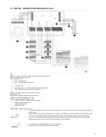
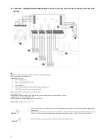
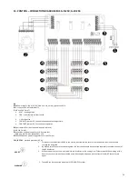
CONTROL – CONNECTION DIAGRAM ELIS G-N-150; G-W-150; G-W-150 2R; G-N-200; G-W-200; G-W-
200 2R.
RX
RX Power supply: 230 V / 50 Hz (OMY min. 3x1,5 mm2); glands 16 x PG11
3 - step switch with thermostat TS
(OMY min. 5x0,5 mm
2
)
•
HEAT – heating mode
•
FAN – room thermostat deactivated
•
COOL – cooling mode
•
1;2;3 step of fan
•
FAN AUTO, jumper 3-5, fan operation depends on temperature,
•
FAN CONT, jumper 4-5, fan continuous operation
Door contact DCm (door opened – opened contacts)
(OMY 2x0,5 mm2);
connection of power supply for ELiS G curtain fans (one connector can be connected to one curtain)
(OMY min. 5x1,0 mm2); glands PG7 + PG9
SRQ/SRQ3d valve power supply (OMY min. 3x0,75 mm
2
)
FK1; FK2; FK3
- overload protector (6,3 A);
ADVICE
1.
To connect the cables from the RX to the curtain, disassemble the cover of the fan box and then lead the cable through
the free gland.
2.
Without a door sensor, the air curtain will work in relation to the setting from TS thermostat. When working with a door
sensor, the curtain will be activated only when the gate is opened (the contacts of the N; DC connector are open).
WARNING
1.
To one RX can be connected maximum of 3 G-W/N-150 or G-W/N-200 curtains
Содержание ELIS G E-150
Страница 36: ...36 56881 MT DTR ELIS G EN PL V2 ...

