13
13.
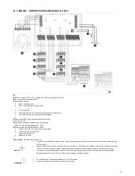
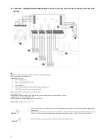
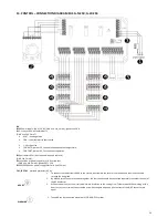
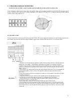
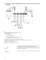
CONTROL – CONNECTION DIAGRAM ELIS G-N-250; G-W-250
RX
RX Power supply: 230 V / 50 Hz (OMY min. 3x1,5 mm2); glands 16 x PG11
3 - step switch with thermostat TS
(OMY min. 5x0,5 mm
2
)
•
HEAT – heating mode
•
FAN – room thermostat deactivated
•
COOL – cooling mode
•
1;2;3 step of fan
•
FAN AUTO, jumper 3-5, fan operation depends on temperature,
•
FAN CONT, jumper 4-5, fan continuous operation
Door contact DCm (door opened – opened contacts)
(OMY 2x0,5 mm2);
connection of power supply for ELiS G curtain fans
(OMY min. 5x1,0 mm2); glands PG7 + PG9
SRQ/SRQ3d valve power supply (OMY min. 3x0,75 mm
2
)
FK1; FK2; FK3
- overload protector (6,3 A);
ADVICE
1.
To connect the cables from the RX to the curtain, disassemble the cover of the fan box and then lead the cable
through the free gland.
2.
By default, three fans are connected together, the fourth one should be connected separately to another channel of
the RX distributor
3.
Without a door sensor, the air curtain will work in relation to the setting from TS thermostat. When working with a
door sensor, the curtain will be activated only when the gate is opened (the contacts of the N; DC connector are
open).
WARNING
1.
To one RX can be connected maximum of 2 G-W/N-250 curtains
Содержание ELIS G E-150
Страница 36: ...36 56881 MT DTR ELIS G EN PL V2 ...

