Flotec FP4105 Скачать руководство пользователя страница 6

Discharge Pipe and Pressure Tank Connections / Electrical 6

For parts or assistance, call Flotec Customer Service at 

1-800-365-6832

STANDARD TANK CONNECTION
(FIGURE 6)

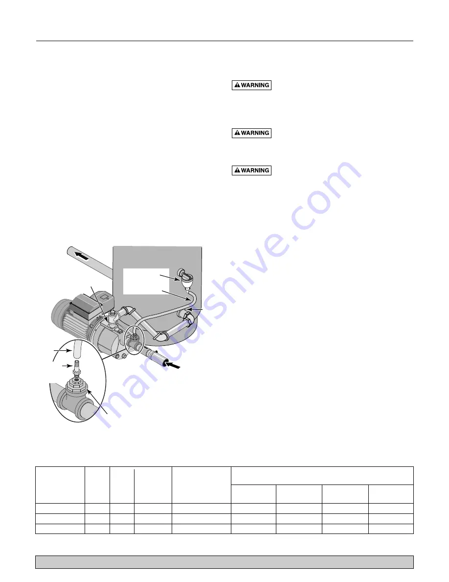
1. Install a tee in the pump discharge port (see Figure 6). 
2. Run a pipe from the pump discharge port to the inlet

port of your tank. The pipe size must be at least as
large as the discharge port.

3. Install a tee with reducing bushings in the suction

pipe as shown in Figure 6.

4. Install a barbed fitting in the smallest bushing 

(1/8" NPT).

5. Run the AVC tubing from the barbed fitting on the suc-

tion pipe tee to the port in the AVC mounted on the
tank. See the instructions provided with the tank and
the AVC for details. The AVC port location may vary. 

Congratulations! You have just completed the tank con-
nection for your jet pump. 

ELECTRICAL

Hazardous voltage. Can shock, burn, or kill.

Connect ground wire before connecting power supply
wires. Use the wire size (including the ground wire) spec-
ified in the wiring chart.

If possible, connect the pump to

a separate branch circuit with no other appliances on it. 

Explosion hazard. Do not ground to a gas

supply line.

Wiring

Fire hazard. 

Incorrect voltage can cause a

fire or seriously damage the motor and voids the warranty.
The supply voltage must be within ±10% of the motor
nameplate voltage. Do not alter the wiring in the motor.
Connect to 115 Volt supply  only.

Install, ground, wire, and maintain your pump in compli-
ance with the National Electrical Code (NEC) or the
Canadian Electrical Code (CEC), as applicable, and with
all local codes and ordinances that apply. Consult your
local building inspector for code information.

Connection Procedure:

Your Pressure Switch looks like one of those shown in
Figure 7. Connect the power supply as shown for your
type of switch.
1. Connect the ground wire first as shown in Figure 7.

The ground wire must be a solid copper wire at least
as large as the power supply wires.

2. There must be a solid metal connection between the

pressure switch and the motor for motor grounding
protection. If the pressure switch is not connected to
the motor, connect the green ground screw in the
switch to the green ground screw under the motor
end cover. Use a solid copper wire at least as large as
the power supply wires.

3. Connect the ground wire to a grounded lead in a ser-

vice panel, to a metal underground water pipe, to a
metal well casing at least ten feet (3M) long, or to a
ground electrode provided by the power company or
the hydro authority.

Distance in Feet (m) from Motor To Supply

Maximum

Branch Wires 

Sizes 

AWG 

(mm

2

)

Load

Circuit Breaker

0-100

101-200

201-300

301-400

Model

HP

Volts

Amps

Rating (Amps)*

(0-30)

(31-61)

(62-91)

(92-122)

FP4105

1/2

115

7.2

15

14 (2)

12 (3)

10 (5.5)

8 (8.4)

FP410515H

1/2

115

7.2

15

14 (2)

12 (3)

10 (5.5)

8 (8.4)

FP4107

3/4

115

8.6

15

14 (2)

10 (5.5)

8 (8.4)

6 (14)

WIRING CHART – RECOMMENDED WIRE AND FUSE SIZES

To Household
Water System

Suction Hose
From Well

Air Volume
Control (AVC)

Tank
Inlet 
Port

AVC Tubing

Pump
Discharge 
Port 

Install a tee in the suction line. Install 
reducing bushings down to 1/8" NPT 
for the barbed fitting. Install the AVC 
tube between the barbed fitting and 
the port on the bottom of the AVC 
(which is mounted on the tank). 

Reducers

AVC
Tube

1/8" NPT
Barbed
Fitting

Figure 6 – Standard Tank Connections

* When using fuses, dual element or Fusetron time delay fuses are recommended for all motor circuits.

Содержание FP4105

Страница 1: ...Operaci n Piezas Para mayor informaci n sobre el funcionamiento instalaci n o mantenimiento de la bomba Llame al 1 800 365 6832 Espa ol Paginas 18 25 2005 FP569 Rev 10 28 05 OWNER S MANUAL Shallow We...

Страница 2: ...ble Sump Pumps 3 Years Models FPSC2200A 10 and FPSC2250A 10 Pre Charge Water System Tank Models FPSC3200A 10 and FPSC3250A 10 5 Years Floodmate 7000 Model FP0S6000A Ironmate Model FPSC4550A Sewage Eje...

Страница 3: ...discharge pipe and tank connections WELL POINT DRIVEN POINT INSTALLATION FIGURE 1 1 Drive the well using drive couplings and a drive cap Drive fittings are threaded all the way through and allow the...

Страница 4: ...e fewest possible fittings especially elbows in the suction pipe The suction pipe should be at least as large as the suction port on the pump 2 Assemble a foot valve and suction pipe see Figure 3 Make...

Страница 5: ...when there is no water in the tank The pre charge should be 2 PSI less than the cut in setting of the pump s pressure switch Congratulations You have just completed the tank con nection for your jet...

Страница 6: ...r local building inspector for code information Connection Procedure Your Pressure Switch looks like one of those shown in Figure 7 Connect the power supply as shown for your type of switch 1 Connect...

Страница 7: ...fting water 25 may take as long as 15 minutes to prime 4 After the pump has built up pressure in the system and shut off check the pressure switch operation by opening a faucet or two and running enou...

Страница 8: ...ow well A deep well pump may be needed over 25 ft to water setup to deliver water to deliver water Pump does not Water level in well is lower than A deep well jet will be needed if your well is more t...

Страница 9: ...Box Base Gasket 1 111P1340 111P1340 9 Seal Plate and Motor 1 10 Seal Plate Insert 1 101P1290 101P1290 11 O Ring 1 111P0700 111P0700 12 Shaft Seal Complete 1 ZBR00010 ZBR00010 13 Impeller 1 731S5700 7...

Страница 10: ...sibles pour puits de 4 pouces Pompes submersibles de puisard de 1 2 ch 3 ans Mod les FPSC2200A 10 et FPSC2250A 10 R servoirs pr charg s de syst me d eau Mod les FPSC3200A 10 et FPSC3250A 10 5 ans Floo...

Страница 11: ...ncement et des chapeaux de battage Les rac cords d enfoncement sont filet s sur toute leur longueur ce qui permet aux extr mit s des tuyaux de venir en but e l une contre l autre de fa on que la force...

Страница 12: ...liser du ruban t flon ou de la p te pour raccords filet s base de t flon sur les raccords filet s Poser une cr pine autour du clapet de pied pour le prot ger contre les poissons les d chets etc voir l...

Страница 13: ...ession d enclenchement du manocontacteur de la pompe F licitations Le branchement de la pompe jecteur sur le r servoir est maintenant termin Pour rendre les raccords des tuyaux tanches N utiliser que...

Страница 14: ...t illustr 1 Brancher tout d abord le fil de mise la terre comme il est illustr la Figure 7 Ce fil de mise la terre doit tre un fil de cuivre massif dont le diam tre sera au moins aussi gros que le dia...

Страница 15: ...ne pompe aspirant de l eau 25 pieds s amorce 4 Apr s que la pression se sera accumul e dans le syst me et que la pompe se sera arr t e v rifier le fonctionnement du manocontacteur en ouvrant un ou deu...

Страница 16: ...la valve ne fuit pas utiliser une solution savonneuse pour cela et au besoin remplacer l obus de la valve Le niveau de l eau du puits est plus bas que celui estim La tuyauterie en acier le cas ch ant...

Страница 17: ...2 po NSPM 1 J43 13C J43 13C Bague de verrouillage de raccord 1 U36 112ZP U36 112ZP 8 Joint de la base de la bo te de c blage 1 111P1340 111P1340 9 Plaque d tanch it et moteur 1 10 Garniture de plaque...

Страница 18: ...UMP de 1 3 HP Modelo FP0S1775A 2 a os Sistema de bomba de sumidero de respaldo Modelo FP2800DCC Bombas de pozo sumergibles de 4 Bombas de sumidero sumergibles de 1 2 HP 3 a os Modelos FPSC2200A 10 y F...

Страница 19: ...ar est n roscadas a todo lo largo y permiten que los extremos de la tuber a empalmen para que la fuerza de perforaci n del mazo sea soportada por la tuber a y no por el enroscado Las conexiones ordina...

Страница 20: ...de tefl n especial para juntas de tuber as den las juntas roscadas de la tuber a Proteja la conexi n de la v lvula de retenci n de peces basura etc con la instalaci n de una malla de alambre a su alr...

Страница 21: ...i n de la bomba Felicidades Usted acaba de realizar la conexi n del tanque para su bomba tipo jet C mo sellar las juntas de tuber a Use solamente cinta de tefl n para hacer todas las conexiones roscad...

Страница 22: ...e corriente seg n se ilustra para su tipo de man stato 1 Conecte el cable de puesta a tierra primero seg n se ilustra en la Figura 7 El cable de puesta a tierra debe ser un cable de cobre macizo por l...

Страница 23: ...de agua de 25 4 Despu s de que la bomba ha producido presi n en el sis tema y est apagada verifique la operaci n del interruptor de presi n abriendo una llave o dos y dejando correr sufi ciente agua p...

Страница 24: ...ario El nivel del agua en el pozo profundo es menor que el que se calcul La tuber a de acero si se utiliz est corro da u oxidada ocasionando una fricci n excesiva El tama o de la tuber a es muy peque...

Страница 25: ...r 1 2 NSPM 1 J43 13C J43 13C Aro de fijaci n del conector 1 U36 112ZP U36 112ZP 8 Empaquetadura de la base de la caja de cables 1 111P1340 111P1340 9 Placa de estanquidad y motor 1 10 Inserci n de la...

Страница 26: ...26...

Страница 27: ...27...

Страница 28: ...28...

Отзывы: