background image

14.15

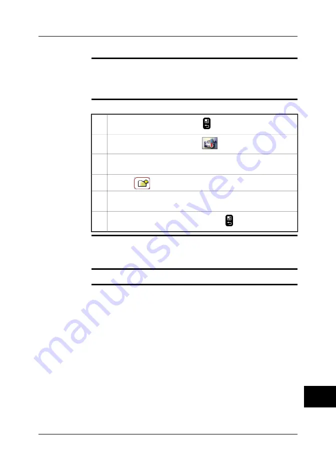
Creating a new work folder

General

You can create new work folders in addition to the preconfigured default work folder.

For example, you may want to create one work folder for each customer, or create
one work folder for each day of an infrared inspection. For large infrared inspections
you may want to create one work folder for each building or application.

Procedure

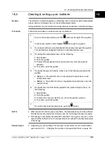
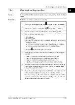
Follow this procedure to create a new work folder:

To go to the mode selector, push the

button to the right of the joystick.

1

In the mode selector, select

Camera

and push the joystick.

2

In the toolbox, go to

Work folder

and push the joystick. This will display a

work folder dialog box.

3

To select

, move the joystick right

4

To create a new work folder, push the joystick. This folder will now be the
default work folder.

5

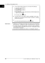
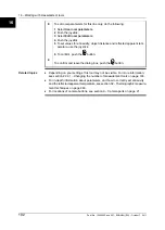
To confirm and leave the dialog box, push the

button.

6

NOTE

You can also create a work folder when the camera is in Archive mode.

To do that, push the joystick to display a menu, and select

Work folder

. Then go to

step 4 above.

Related topics

For locations of camera buttons, see section 9 – Camera parts on page 21.

14

Publ. No. 1558550 Rev. a557 – ENGLISH (EN) – October 7, 2011

87

14 – Working with views and images

Содержание B6 series

Страница 1: ...User s manual FLIR B6xx series FLIR P6xx series FLIR SC6xx series 1558550 Publ No a557 Revision English EN Language October 7 2011 Issue date...

Страница 2: ......

Страница 3: ...es 4 Important note about this manual 5 Parts lists 6 Quick Start Guide 7 A note about ergonomics 8 Camera parts 9 Screen elements 10 Connecting external devices 11 Pairing Bluetooth devices 12 Handli...

Страница 4: ......

Страница 5: ...20 Recording video clips 21 Changing settings 22 Cleaning the camera 23 Technical data 24 Finding the IP address for a camera connected using a FireWire cable 25 Dimensional drawings 26 Application ex...

Страница 6: ......

Страница 7: ...Glossary 31 Thermographic measurement techniques 32 History of infrared technology 33 Theory of thermography 34 The measurement formula 35 Emissivity tables 36...

Страница 8: ......

Страница 9: ...User s manual Publ No 1558550 Rev a557 ENGLISH EN October 7 2011...

Страница 10: ...er legal theory This warranty shall be governed by Swedish law Any dispute controversy or claim arising out of or in connection with this warranty shall be finally settled by arbitration in accordance...

Страница 11: ...NTIRE RISK AS TO SAT ISFACTORY QUALITY PERFORMANCE ACCURACY AND EFFORT INCLUDING LACK OF NEGLIGENCE IS WITH YOU ALSO THERE IS NO WARRANTY AGAINST INTERFERENCE WITH YOUR ENJOYMENT OF THE SOFTWARE OR AG...

Страница 12: ...INTENTIONALLY LEFT BLANK xii Publ No 1558550 Rev a557 ENGLISH EN October 7 2011...

Страница 13: ...images 35 11 Connecting external devices 36 11 1 Connecting devices to the rear connectors 38 11 2 Connecting devices to the front connector 39 11 3 Inserting SD Memory Cards 41 12 Pairing Bluetooth...

Страница 14: ...70 14 2 Saving an image 71 14 3 Opening an image 72 14 4 Using the zoom function 73 14 5 Using the Panorama function 75 14 6 Using the pan function 76 14 7 Adjusting an image 79 14 8 Changing maximum...

Страница 15: ...ork 138 22 3 3 Connecting the camera using a infrastructure WLAN network 139 22 3 4 Changing Wi Fi settings 140 22 3 5 Changing settings for the laser 141 22 3 6 Enabling or disabling GPS 142 22 3 7 C...

Страница 16: ...7 2 Faulty contact in socket 183 27 3 Oxidized socket 184 27 4 Insulation deficiencies 185 27 5 Draft 187 28 Introduction to building thermography 187 28 1 Disclaimer 187 28 1 1 Copyright notice 187 2...

Страница 17: ...sulation continuity UK example 222 28 4 8 1 Credits 223 28 4 8 2 Introduction 223 28 4 8 3 Background information 224 28 4 8 4 Quantitative appraisal of thermal anomalies 227 28 4 8 5 Conditions and e...

Страница 18: ...31 Glossary 263 32 Thermographic measurement techniques 263 32 1 Introduction 263 32 2 Emissivity 264 32 2 1 Finding the emissivity of a sample 264 32 2 1 1 Step 1 Determining reflected apparent tempe...

Страница 19: ...ect the interference by one or more of the following measures Reorient or relocate the receiving antenna Increase the separation between the equipment and receiver Connect the equipment into an outlet...

Страница 20: ...otect the laser pointer with the protective cap when you do not operate the laser pointer Applies only to cameras with battery Do not attach the batteries directly to a car s cigarette lighter socket...

Страница 21: ...to the camera the cables or other items This can cause damage Be careful when you clean the infrared lens The lens has a delicate anti reflective coating Do not clean the infrared lens too vigorously...

Страница 22: ...INTENTIONALLY LEFT BLANK 1 4 Publ No 1558550 Rev a557 ENGLISH EN October 7 2011 1 Warnings Cautions...

Страница 23: ...Contact your local sales office for instructions on where to send the camera Accuracy This notice only applies to cameras with measurement capabilities For very accurate results we recommend that you...

Страница 24: ...INTENTIONALLY LEFT BLANK 2 6 Publ No 1558550 Rev a557 ENGLISH EN October 7 2011 2 Notice to user...

Страница 25: ...hat you have the following informa tion to hand The camera model The camera serial number The communication protocol or method between the camera and your PC for example HDMI Ethernet USB or FireWire...

Страница 26: ...INTENTIONALLY LEFT BLANK 3 8 Publ No 1558550 Rev a557 ENGLISH EN October 7 2011 3 Customer help...

Страница 27: ...sis To access the latest manuals and notifications go to the Download tab at http support flir com It only takes a few minutes to register online In the download area you will also find the latest rel...

Страница 28: ...INTENTIONALLY LEFT BLANK 4 10 Publ No 1558550 Rev a557 ENGLISH EN October 7 2011 4 Documentation updates...

Страница 29: ...is manual may contain descriptions and explanations that do not apply to your particular camera model NOTE FLIR Systems reserves the right to discontinue models software parts or accessories and other...

Страница 30: ...INTENTIONALLY LEFT BLANK 5 12 Publ No 1558550 Rev a557 ENGLISH EN October 7 2011 5 Important note about this manual...

Страница 31: ...aining brochure Shoulder strap software CD ROM USB cable User documentation CD ROM Video cable Warranty extension card or Registration card Wi Fi USB micro adapter depending on CE and FCC regulations...

Страница 32: ...pers ITC CER 5109 ITC Level 1 Thermography Course group of 10 pers ITC CER 5201 ITC Level 2 Thermography Course attendance 1 pers ITC CER 5205 ITC Level 2 Thermography Course additional student to on...

Страница 33: ...series T197189 IR lens f 19 mm 45 incl case for FLIR 600 series T197190 IR lens f 131 mm 7 incl case for FLIR 600 series T197230 Remote control unit T197262 Hard transport case for FLIR B P SC6xx T197...

Страница 34: ...73 MO297 Moisture meter pinless with memory T951235 Bluetooth USB micro adapter T951387 Wi Fi USB micro adapter NOTE FLIR Systems reserves the right to discontinue models parts or accessories and othe...

Страница 35: ...the center of the button 8 To save an image directly push and hold the button for more than one second 9 To move the image to a computer do one of the following Remove the SD Memory Card and insert i...

Страница 36: ...INTENTIONALLY LEFT BLANK 7 18 Publ No 1558550 Rev a557 ENGLISH EN October 7 2011 7 Quick Start Guide...

Страница 37: ...ys tilt the viewfinder to fit your work position Always adjust the viewing angle of the display to fit your work position Always adjust the camera grip to fit your work position When you hold the came...

Страница 38: ...usting the viewing angle of the viewfinder on page 56 Section 13 11 Adjusting the camera grip on page 58 Section 13 13 Adjusting the viewing angle of the display on page 60 8 20 Publ No 1558550 Rev a5...

Страница 39: ...ing an infrared lens on page 62 1 Digital camera 2 Laser pointer For more information see section 9 6 Laser pointer on page 29 3 Lamp for digital camera 4 Laser button The Laser button has the followi...

Страница 40: ...histogram and detail modes Switch between active measurement tools Switch fusion on and off Switch lamp on and off Switch between infrared camera and digital camera Switch between the current and refe...

Страница 41: ...utton has the following functions To preview an image push and release the button To save an image push and hold the button for more than one second For more information see the following Section 14 1...

Страница 42: ...mode To adjust focus push the button left right To autofocus the camera push the center of the Focus button When an image is in preview or recall mode To adjust zoom push the button left right For mor...

Страница 43: ...on page 55 2 Release button for lid to connector compartment For more information see section 11 Connecting external devices on page 35 3 Lid for connector compartment For more information see section...

Страница 44: ...is on push and hold for more than two seconds to turn off the camera When the camera is on push and release to go to power save mode For more information see the following Section 13 5 Turning on the...

Страница 45: ...Explanation Type of signal The battery is being charged The green LED flashes two times per second The battery is fully charged The green LED glows continuously The power supply or the stand alone bat...

Страница 46: ...e gives an explanation to the power LED indicator Explanation Type of signal The camera is off The LED is off The camera is in stand by mode The LED is orange The camera is on The LED is green 9 28 Pu...

Страница 47: ...an cause eye irritation CAUTION Protect the laser pointer with the protective cap when you do not operate the laser pointer NOTE The symbol is displayed on the screen when the laser pointer is on The...

Страница 48: ...the camera 10743603 a2 Laser rules and regulations Wavelength 635 nm Max output power 1 mW This product complies with 21 CFR 1040 10 and 1040 11 except for deviations pur suant to Laser Notice No 50 d...

Страница 49: ...nalyze save IR images 1 Archive mode View saved images video clip 2 Program mode Save images automatically 3 Setup mode Set up camera 4 Video mode Record non radiometric video clips 5 Sequence mode Re...

Страница 50: ...lanation This table gives an explanation to the figure above Result table 1 Line measurement tool 2 Box measurement tool 3 Circle measurement tool 4 Status bar 5 Temperature scale 6 Isotherm measureme...

Страница 51: ...information field 5 SD Memory Card indicator I or II The indicator also shows the amount of free space on the SD Memory Card As a warning the indicator will turn yellow and then red as the amount of f...

Страница 52: ...explains the screen elements in infrared images in Archive mode only Image description Text annotation Fusion Voice annotation Panorama Image link indicating associated panorama images 10 34 Publ No...

Страница 53: ...th micro adapter to connect to a headset or a USB WLAN micro adapter to connect the camera to a remote control P N T197230 A headset to record and listen to voice comments One or two SD Memory Cards W...

Страница 54: ...e and this connector This connector is also used when pairing the camera to the remote control P N T197230 2 To connect a computer for recording infrared sequences at high speed use a FireWire cable a...

Страница 55: ...supply to the camera use the power supply cable and this connector The power connector is protected by a rubber cover 1 Related topics For information about pin configuration see section 24 Technical...

Страница 56: ...explanation to the figure above To connect a headset to the camera use the headset cable and this con nector 1 Related topics For information about pin configuration see section 24 Technical data on...

Страница 57: ...rmatting memory cards For best performance memory cards should be formatted to the FAT FAT16 file system Using FAT32 formatted memory cards may result in inferior performance To format a memory card t...

Страница 58: ...card slot marked I This card slot has a higher file transfer rate than the card slot marked II SDHC Memory Cards that are 4 GB or larger can only be formatted to the FAT32 file system 11 40 Publ No 15...

Страница 59: ...onnector 1 Turn on the camera 2 To go to the mode selector push the button to the right of the joystick 3 In the mode selector select Setup and push the joystick 4 In the toolbox select Bluetooth 5 To...

Страница 60: ...INTENTIONALLY LEFT BLANK 12 42 Publ No 1558550 Rev a557 ENGLISH EN October 7 2011 12 Pairing Bluetooth devices...

Страница 61: ...this procedure to charge the battery using the power supply cable Connect the power supply cable plug to the connector on the battery 1 Connect the power supply wall plug to a mains supply 2 When the...

Страница 62: ...Put the battery in the stand alone battery charger 1 Connect the power supply cable plug to the connector on the stand alone battery charger 2 Connect the power supply wall plug to a mains supply 3 Wh...

Страница 63: ...en it is inside the remote control Use the combined power supply and battery charger to charge the battery when it is outside the remote control SEE For information on how to charge the battery see th...

Страница 64: ...o use the power supply to charge the battery when it is inside the remote control Open the battery compartment cover 1 Connect the power supply cable plug to the connector on the battery 2 Connect the...

Страница 65: ...o use the power supply to charge the battery when it is outside the remote control Put the battery on a flat surface 1 Connect the power supply cable plug to the connector on the battery 2 Connect the...

Страница 66: ...or moisture on the battery before you install it Procedure Follow this procedure to install the battery Align the battery with the battery slot 10728903 a2 1 Push the battery into position until the...

Страница 67: ...nter clockwise to access the release button for the battery locking mechanism 10729303 a1 1 Push the release button for the battery locking mechanism up 10729103 a1 2 Pull out the battery from the bat...

Страница 68: ...nsert it Procedure Follow this procedure to install the battery Push the release button on the battery compartment cover to unlock it 10759603 a1 1 Open the cover to the battery compartment 10759703 a...

Страница 69: ...Close the cover to the battery compartment 10759903 a1 4 13 Publ No 1558550 Rev a557 ENGLISH EN October 7 2011 51 13 Handling the camera...

Страница 70: ...release button on the battery compartment cover to unlock it 10759603 a1 1 Open the cover to the battery compartment 10763903 a1 2 Push the red release button in the direction of the arrow to unlock t...

Страница 71: ...Pull out the battery from the battery compartment 10760103 a1 4 13 Publ No 1558550 Rev a557 ENGLISH EN October 7 2011 53 13 Handling the camera...

Страница 72: ...tions of camera buttons see section 9 Camera parts on page 21 13 7 Setting power save mode Procedure When the camera is on push and release the On Off button to set power save mode NOTE If you do not...

Страница 73: ...or right eye Procedure Follow this procedure to adjust the viewfinder eyepiece Pull the rubber eyepiece 10739203 a1 1 Rotate the rubber eyepiece 180 10739303 a1 2 Push the rubber eyepiece back into po...

Страница 74: ...your working position as comfortable as possible you can adjust the viewing angle of the viewfinder Figure 10729403 a1 Procedure To adjust the viewfinder tilt the viewfinder up or down 13 56 Publ No...

Страница 75: ...9503 a1 Procedure To adjust the viewfinder s dioptric correction look at the displayed text or graphics on the screen and rotate the adjustment knob clockwise or counter clockwise for best sharpness N...

Страница 76: ...tion as comfortable as possible you can adjust the angle of the camera grip Figure 10729603 a1 Procedure To adjust the camera grip rotate the camera grip clockwise or counter clockwise 13 58 Publ No 1...

Страница 77: ...Open the display 10729803 a2 2 NOTE The viewfinder will automatically turn off when you open the display You can change this behavior by modifying the display settings Related topics Section 22 3 8 Ch...

Страница 78: ...tion as comfortable as possible you can adjust the viewing angle of the display Figure 10729903 a1 Procedure To adjust the viewing angle of the display rotate the display clockwise or counter clockwis...

Страница 79: ...on page 152 Procedure Follow this procedure to install an infrared lens Align the index mark on the lens with the index mark on the bayonet ring 10730403 a1 1 Carefully push the infrared lens into th...

Страница 80: ...he lens caps on the lens to protect it from dust and fingerprints Procedure Follow this procedure to remove an infrared lens Push the release button for the infrared lens forward 10739103 a1 1 Rotate...

Страница 81: ...cording to the instructions in section 23 2 Infrared lens on page 152 Figure 10730003 a1 Procedure Do one of the following For far focus rotate the focus ring counter clockwise looking at the front of...

Страница 82: ...infrared camera focus Make sure that the image is in live mode 1 To adjust the camera focus push the button left right 2 Related topics For locations of camera buttons see section 9 Camera parts on p...

Страница 83: ...of camera buttons see section 9 Camera parts on page 21 For information on how to adjust the infrared camera focus see section 13 16 Adjusting the infrared camera focus manually on page 63 You can als...

Страница 84: ...you autofocus the infrared image Procedure To autofocus the digital camera when you are in visual mode push the center of the button Related topics For locations of camera buttons see section 9 Camera...

Страница 85: ...n 1 To turn off the laser pointer release the laser button 2 NOTE The laser pointer may not be enabled in all markets An indicator on the screen shows the position of the laser dot Related topics Sect...

Страница 86: ...INTENTIONALLY LEFT BLANK 13 68 Publ No 1558550 Rev a557 ENGLISH EN October 7 2011 13 Handling the camera...

Страница 87: ...it In preview mode you can also manipulate the image before you save it Procedure To preview an image push and release the Preview Save button NOTE You can also preview an infrared image and a digital...

Страница 88: ...Procedure To save an image from live or preview mode push and hold the Preview Save button for more than one second NOTE You can specify the folder to use when saving an image by specifying a default...

Страница 89: ...ive and push the joystick 2 Do one of the following To select a different image move the joystick left right To see an overview of all images push the Focus button and do the following 1 To select the...

Страница 90: ...right You can also select Zoom Pan in the toolbox and push the joystick up down to adjust zoom NOTE When you save the image again the zoom factor will be saved too To save the image push the Preview S...

Страница 91: ...s procedure To go to the mode selector push the button to the right of the joystick 1 In the mode selector select Camera and push the joystick 2 Go to the right most tab Application using the joystick...

Страница 92: ...a1 5 Using the joystick you can now decide in which area you want to save the next image and then save the image by pushing the Preview Save button Continue with this procedure until you have created...

Страница 93: ...ion When the image is in preview mode or archive mode select Zoom Pan in the toolbox 1 Push the joystick to go to pan mode 2 To pan over the image push the joystick left right or up down 3 NOTE When y...

Страница 94: ...left cable is difficult to do if you only auto adjust the image You can analyze the left cable in more detail if you change the temperature scale level change the temperature scale span In the image...

Страница 95: ...recorded at a minimum temperature of 26 0 C 14 8 F In the right image the maximum and minimum temperature levels have been changed to temperature levels near the iso lator This makes it easier to ana...

Страница 96: ...ck up down 4 Changing temperature scale span Follow this procedure to change the temperature scale span 1 To go to the mode selector push the button to the right of the joystick In the mode selector s...

Страница 97: ...nes in front of a clear sky In this case you want to use as many colors as possible for your object and as few as possible for the background To do this specify a temperature slightly below the temper...

Страница 98: ...the joystick In the mode selector select Camera and push the joystick 2 To hide overlay graphics select Hide graphics in the toolbox 3 NOTE If you want to display or hide only some individual graphics...

Страница 99: ...palette move the joystick up down to select the palette To invert the invert the palette move the joystick up down to select Invert palette To enable or disable saturation colors select Saturation col...

Страница 100: ...ode selector push the button to the right of the joystick 1 In the Mode selector select Archive and push the joystick 2 To see an overview of all images push the Focus button 3 To go to the image you...

Страница 101: ...want to set as reference image move the joystick left right 3 To display a menu push the joystick 4 On the menu select Set as reference image to set the image as a reference image 5 Setting reference...

Страница 102: ...t the currently displayed image as a reference image 3 Switching reference image In the toolbox select Switch reference image to switch between the current image and the reference image Clearing refer...

Страница 103: ...n a camera with two image folders as seen from Windows Explorer The camera is the top node in the folder structure Ircam0741 The camera handles images more efficiently if a folder structure is used Sa...

Страница 104: ...k folder and push the joystick This will display a work folder dialog box 3 To select the work folder you want the camera to use move the joystick up down 4 To confirm the choice push the joystick 5 T...

Страница 105: ...ck 1 In the mode selector select Camera and push the joystick 2 In the toolbox go to Work folder and push the joystick This will display a work folder dialog box 3 To select move the joystick right 4...

Страница 106: ...der you want to delete move the joystick up down 4 To select move the joystick right and then up down 5 To delete the work folder push the joystick To confirm and leave the dialog box push the button...

Страница 107: ...the joystick to delete the currently displayed image Push the Focus button and do the following 1 Move the joystick left right or up down to select the image you want to delete 2 To display a menu pu...

Страница 108: ...on and do the following 1 Move the joystick left right or up down to select the image you want to delete 2 To display a menu push the joystick 3 To delete the selected image select Delete all on the m...

Страница 109: ...the size of the image frame Fusion types Depending on camera model up to four different types of fusion are available These are Above All areas in the digital photo with a temperature above the specif...

Страница 110: ...e examples This table explains the four different types of fusion Image Fusion type Above Below Interval Picture in Picture 15 92 Publ No 1558550 Rev a557 ENGLISH EN October 7 2011 15 Working with fus...

Страница 111: ...below If you chose Interval do one or more of the following Push the joystick up down to move the interval up down Push the joystick left right to increase decrease the interval If you chose Picture i...

Страница 112: ...INTENTIONALLY LEFT BLANK 15 94 Publ No 1558550 Rev a557 ENGLISH EN October 7 2011 15 Working with fusion...

Страница 113: ...ter temperature as a reference temperature select Set as reference temperature and push the joystick to confirm Note For a box circle or line you can only use this command if Max Min or Avg is active...

Страница 114: ...sivity and the reflected apparent temperature see section 32 Thermographic measure ment techniques on page 263 For locations of camera buttons see section 9 Camera parts on page 21 16 96 Publ No 15585...

Страница 115: ...push the button 5 To specify type of result select one or more of the following and push the joystick to confirm Max i e returns the maximum temperature inside the box or circle Min i e returns the m...

Страница 116: ...is see section 18 Working with alarms on page 111 10 To confirm and leave the dialog box push the button 11 Related topics Depending on your settings this tool may not be visible For more information...

Страница 117: ...and push the joystick Above i e the isotherm color is only applied to pixels above a set temperature level Below i e the isotherm color is only applied to pixels below a set tem perature level 5 To sp...

Страница 118: ...sivity and the reflected apparent temperature see section 32 Thermographic measure ment techniques on page 263 For locations of camera buttons see section 9 Camera parts on page 21 16 100 Publ No 1558...

Страница 119: ...he joystick 4 To specify type of result select one of the following and push the joystick to confirm Max i e returns the maximum temperature along the line Min i e returns the minimum temperature alon...

Страница 120: ...push the button 9 Related topics Depending on your settings this tool may not be visible For more information see section 22 2 1 Changing the number of measurement tools on page 133 For in depth info...

Страница 121: ...To select the result type of the measurement tool select Type and push the joystick Move the joystick up down to select the result type of the measurement tool 4 Do the following and push the joystic...

Страница 122: ...vity Object distance i e the distance between the camera and the object of interest Atmospheric temperature i e the temperature of the air between the camera and the object of interest Relative humidi...

Страница 123: ...d push the joystick 3 To confirm and leave the dialog box push the button 4 NOTE Of the seven parameters above emissivity and reflected apparent temperature are the two most important to set correctly...

Страница 124: ...INTENTIONALLY LEFT BLANK 16 106 Publ No 1558550 Rev a557 ENGLISH EN October 7 2011 16 Working with measurement tools...

Страница 125: ...ical support for Extech meters support extech com This support is for Extech meters only For technical support for infrared cameras go to http support flir com NOTE This procedure assumes that you hav...

Страница 126: ...following To preview an image push the Preview Save button At this stage you can add additional values To do so take a new measurement with the meter and select Add on the infrared camera screen To s...

Страница 127: ...been found 2 When a spot of particular interest is located store the moisture reading in the moisture meter s memory and identify the measurement spot with a handprint or other thermal identifying ma...

Страница 128: ...INTENTIONALLY LEFT BLANK 17 110 Publ No 1558550 Rev a557 ENGLISH EN October 7 2011 17 Fetching data from external Extech meters...

Страница 129: ...ar way Procedure Follow this procedure to set up an alarm To go to the mode selector push the button to the right of the joystick 1 In the mode selector select Camera and push the joystick 2 To create...

Страница 130: ...Related topics For locations of camera buttons see section 9 Camera parts on page 21 18 112 Publ No 1558550 Rev a557 ENGLISH EN October 7 2011 18 Working with alarms...

Страница 131: ...re there is risk of humidity falling out as liquid water i e where the relative humidity is 100 To detect areas where the relative humidity is less than 100 you can use the Relative humidity alarm whe...

Страница 132: ...larm will now be triggered when the conditions you have set for the alarm are met 6 NOTE When a building alarm is activated all other measurement tools are inactivated SEE ALSO For information about t...

Страница 133: ...tions below describe how to add various kinds of annotations but for even higher work efficiency you should consider setting up the camera to automatically ask for annotations For information on how t...

Страница 134: ...ge saving on page 134 Procedure Follow this procedure to take a digital photo To preview an infrared image push the Preview Save button 1 To save the previewed infrared image push and hold the Preview...

Страница 135: ...ally ask for a voice annotation For information on how to do this see section 22 2 2 Changing settings for image saving on page 134 Procedure Follow this procedure to create a voice annotation To prev...

Страница 136: ...section 22 2 2 Changing settings for image saving on page 134 NOTE Some buttons have more than one function and the symbols on the buttons will change depending on context 19 118 Publ No 1558550 Rev...

Страница 137: ...r in several ways A text annotation is a proprietary annotation format from FLIR Systems and the information cannot be retrieved by other vendors software An image description uses a standard tag in t...

Страница 138: ...ol 2 Tool 3 Recommendation Recommendation 1 Recommendation 2 Recommendation 3 NOTE This procedure assumes that the camera is set up to automatically ask for a text an notation For information on how t...

Страница 139: ...eview Save button 4 Related topics For locations of camera buttons see section 9 Camera parts on page 21 To set up the camera to save a text annotation see section 22 2 2 Changing settings for image s...

Страница 140: ...at the time when the image is saved However the image description can be edited in a Pocket PC using Pocket Word before it is beamed to the camera Valid file format txt i e plain ANSI text document ps...

Страница 141: ...m and leave the dialog box push the button 4 Related topics For locations of camera buttons see section 9 Camera parts on page 21 19 Publ No 1558550 Rev a557 ENGLISH EN October 7 2011 123 19 Annotatin...

Страница 142: ...INTENTIONALLY LEFT BLANK 19 124 Publ No 1558550 Rev a557 ENGLISH EN October 7 2011 19 Annotating images...

Страница 143: ...the following 1 Move the joystick up down to select Hours Minutes and Seconds re spectively 2 For each parameter push the joystick 3 For each parameter move the joystick up down to set a value 4 For e...

Страница 144: ...INTENTIONALLY LEFT BLANK 20 126 Publ No 1558550 Rev a557 ENGLISH EN October 7 2011 20 Programming the camera...

Страница 145: ...infrared camera DC digital camera Push the joystick to confirm 3 Do one or more of the following and push the joystick to confirm each choice Some buttons have more than one function To start a record...

Страница 146: ...x D4 Decoder which is a MPEG 4 toolkit that supports MPEG 4 Video MPEG 4 Audio and the MP4 file format You can download the 3ivx D4 Decoder from http www 3ivx com Related topics For location of button...

Страница 147: ...quence settings use the joystick Push the joystick to confirm each choice 3 To confirm and leave the dialog box push the button 4 Do one or more of the following and push the joystick to confirm each...

Страница 148: ...en you work with radiometric infrared sequence files This gives better performance Related topics For location of buttons see section 9 Camera parts on page 21 21 130 Publ No 1558550 Rev a557 ENGLISH...

Страница 149: ...ct temperature range of the camera To go to the mode selector push the button to the right of the joystick 1 In the mode selector select Camera and push the joystick 2 In the toolbox select Temperatur...

Страница 150: ...application the best Procedure Follow this procedure to change settings for image enhancement filters To go to the mode selector push the button to the right of the joystick 1 In the mode selector sel...

Страница 151: ...ber of measurement tools To go to the mode selector push the button to the right of the joystick 1 In the mode selector select Setup and push the joystick 2 In the toolbox select Tools 3 For each meas...

Страница 152: ...o go to Picture in Picture mode after saving an infrared image JPEG Compression i e to change the compression of images Associate images i e to associate digital photos with infrared images Simultaneo...

Страница 153: ...Switch fusion on and off Switch lamp on and off Switch between infrared camera and digital camera Switch between the current and reference images Procedure Follow this procedure to specify which func...

Страница 154: ...is the easiest method for moving images to and from the camera It requires no special software to be installed on the computer but the camera functionality is very limited while connected to the PC N...

Страница 155: ...the camera 1 Turn on the camera 2 To go to the mode selector push the button to the right of the joystick 3 In the mode selector select Setup and push the joystick 4 In the toolbox select Communicatio...

Страница 156: ...WLAN SD Card a USB WLAN micro adapter or a USB Wi Fi micro adapter is inserted into the camera Procedure Follow this procedure Insert a USB Wi Fi micro adapter into the camera 1 Turn on the camera 2 T...

Страница 157: ...ent channel use the joystick Push the joystick to confirm each choice You can use channels 1 to 11 However since the channels overlap only channels 1 6 and 11 are normally used 5 In the other device r...

Страница 158: ...l The camera will set the image level to the temperature of the object at the laser dot Sticky spot A spot will be placed at the position of the laser dot which will then move with the laser dot and r...

Страница 159: ...x select GPS 3 To enable or disable GPS use the joystick Push the joystick to confirm each choice 4 To confirm and leave the dialog box push the button 5 NOTE GPS data are displayed at the bottom of t...

Страница 160: ...turn off To go to the mode selector push the button to the right of the joystick 1 In the mode selector select Setup and push the joystick 2 In the toolbox select Power and push the joystick 3 To sel...

Страница 161: ...he display automatically turn on and the viewfinder automati cally turn off when you open the display select Auto To turn on the display and override the previous behavior select Display To turn on th...

Страница 162: ...box select Video 3 Do the following 1 To enter edit mode push the joystick 2 To change the setting push the joystick up down 3 To confirm the choice push the joystick 4 To confirm and leave the dialog...

Страница 163: ...on to the right of the joystick 1 In the mode selector select Setup and push the joystick 2 In the toolbox select View and push the joystick 3 To specify which information will be displayed on the sta...

Страница 164: ...exts are displayed To go to the mode selector push the button to the right of the joystick 1 In the mode selector select Setup and push the joystick 2 In the toolbox select Menu and push the joystick...

Страница 165: ...al settings To go to the mode selector push the button to the right of the joystick 1 In the mode selector select Setup and push the joystick 2 In the toolbox select Regional and push the joystick 3 T...

Страница 166: ...to the right of the joystick 1 In the mode selector select Setup and push the joystick 2 In the toolbox select Date time and push the joystick 3 To change the date time and time zone use the joystick...

Страница 167: ...lowing To save a user profile move the joystick right and then up down to select and then push the joystick To load a user profile move the joystick right and then up down to select and then push the...

Страница 168: ...e sure that you move the complete Profile XXXX folder Do not touch the files inside the folder Related topics For locations of camera buttons see section 9 Camera parts on page 21 22 150 Publ No 15585...

Страница 169: ...ion Equipment A soft cloth Procedure Follow this procedure Soak the cloth in the liquid 1 Twist the cloth to remove excess liquid 2 Clean the part with the cloth 3 CAUTION Do not apply solvents or sim...

Страница 170: ...he lens one time only and discard the cotton wool 3 WARNING Make sure that you read all applicable MSDS Material Safety Data Sheets and warning labels on containers before you use a liquid the liquids...

Страница 171: ...owing this procedure the infrared detector must be cleaned mechanically This mechanical cleaning must be carried out by an authorized service partner CAUTION In Step 2 below do not use pressurized air...

Страница 172: ...INTENTIONALLY LEFT BLANK 23 154 Publ No 1558550 Rev a557 ENGLISH EN October 7 2011 23 Cleaning the camera...

Страница 173: ...For technical data refer to the datasheets on the user documentation CD ROM that comes with the camera Technical data is also available at http support flir com 24 Publ No 1558550 Rev a557 ENGLISH EN...

Страница 174: ...tor 10730903 a2 Signal name Pin 12V 1 GND 2 GND 3 Pin configuration for headset connector 10731003 a1 Signal name Pin MICROPHONE 1 MICROPHONE 2 EARPHONE 3 EARPHONE 4 Field of view 24 156 Publ No 15585...

Страница 175: ...to targets for a 45 19 mm lens D distance to target 10733403 a2 Field of view distance 24 40 mm lens 10732003 a1 Figure 24 2 Relationship between field of view and distance 1 Distance to target 2 VFOV...

Страница 176: ...target 2 VFOV vertical field of view 3 HFOV horizontal field of view 4 IFOV instan taneous field of view size of one detector element This table specifies the field of view at certain distances to ta...

Страница 177: ...l number and write it down The address for the camera is ircamXXXX where XXXX are the four last figures in the serial number 2 Method 2 Connect the camera to a computer using the FireWire cable 1 On t...

Страница 178: ...INTENTIONALLY LEFT BLANK 25 160 Publ No 1558550 Rev a557 ENGLISH EN October 7 2011 25 Finding the IP address for a camera connected using a FireWire cable...

Страница 179: ...26 Dimensional drawings 26 1 Camera 26 1 1 Camera dimensions front view excl lens Figure 10733603 a2 26 Publ No 1558550 Rev a557 ENGLISH EN October 7 2011 161...

Страница 180: ...26 1 2 Camera dimensions side view excl lens Figure 10731103 a1 26 162 Publ No 1558550 Rev a557 ENGLISH EN October 7 2011 26 Dimensional drawings...

Страница 181: ...26 1 3 Camera dimensions side view incl 45 19 mm lens Figure 10731303 a1 26 Publ No 1558550 Rev a557 ENGLISH EN October 7 2011 163 26 Dimensional drawings...

Страница 182: ...26 1 4 Camera dimensions side view incl 24 40 mm lens Figure 10731203 a1 26 164 Publ No 1558550 Rev a557 ENGLISH EN October 7 2011 26 Dimensional drawings...

Страница 183: ...26 1 5 Camera dimensions side view incl 12 76 mm lens Figure 10755403 a1 26 Publ No 1558550 Rev a557 ENGLISH EN October 7 2011 165 26 Dimensional drawings...

Страница 184: ...26 1 6 Camera dimensions side view incl close up lens P N 1196683 mounted on a 40 mm lens Figure 10755603 a1 26 166 Publ No 1558550 Rev a557 ENGLISH EN October 7 2011 26 Dimensional drawings...

Страница 185: ...7 Camera dimensions position of tripod mount incl 45 19 mm lens Figure 10731603 a2 NOTE The tripod mount thread is 1 4 20 26 Publ No 1558550 Rev a557 ENGLISH EN October 7 2011 167 26 Dimensional draw...

Страница 186: ...8 Camera dimensions position of tripod mount incl 24 40 mm lens Figure 10731503 a2 NOTE The tripod mount thread is 1 4 20 26 168 Publ No 1558550 Rev a557 ENGLISH EN October 7 2011 26 Dimensional draw...

Страница 187: ...9 Camera dimensions position of tripod mount incl 12 76 mm lens Figure 10755503 a1 NOTE The tripod mount thread is 1 4 20 26 Publ No 1558550 Rev a557 ENGLISH EN October 7 2011 169 26 Dimensional draw...

Страница 188: ...s position of tripod mount incl close up lens P N 1196683 mounted on a 24 40 mm lens Figure 10755703 a1 NOTE The tripod mount thread is 1 4 20 26 170 Publ No 1558550 Rev a557 ENGLISH EN October 7 2011...

Страница 189: ...11 Camera dimensions distance from tripod mount to optical center Figure 10740903 a1 NOTE The tripod mount thread is 1 4 20 26 Publ No 1558550 Rev a557 ENGLISH EN October 7 2011 171 26 Dimensional dra...

Страница 190: ...era battery Figure 10731703 a2 NOTE Use a clean dry cloth to remove any water or moisture on the battery before you install it 26 172 Publ No 1558550 Rev a557 ENGLISH EN October 7 2011 26 Dimensional...

Страница 191: ...26 3 1 Stand alone battery charger excl battery Figure 10731803 a1 NOTE Use a clean dry cloth to remove any water or moisture on the battery before you install 26 Publ No 1558550 Rev a557 ENGLISH EN...

Страница 192: ...it 26 174 Publ No 1558550 Rev a557 ENGLISH EN October 7 2011 26 Dimensional drawings...

Страница 193: ...tery charger incl battery Figure 10731903 a2 NOTE Use a clean dry cloth to remove any water or moisture on the battery before you install it 26 Publ No 1558550 Rev a557 ENGLISH EN October 7 2011 175 2...

Страница 194: ...26 4 Remote control 26 4 1 Remote control dimensions front view Figure T630241 a1 26 176 Publ No 1558550 Rev a557 ENGLISH EN October 7 2011 26 Dimensional drawings...

Страница 195: ...26 4 2 Remote control dimensions side view Figure T630242 a1 26 Publ No 1558550 Rev a557 ENGLISH EN October 7 2011 177 26 Dimensional drawings...

Страница 196: ...26 4 3 Remote control dimensions top view Figure T630243 a1 26 178 Publ No 1558550 Rev a557 ENGLISH EN October 7 2011 26 Dimensional drawings...

Страница 197: ...control battery Figure 10602103 a2 NOTE Use a clean dry cloth to remove any water or moisture on the battery before you install it 26 Publ No 1558550 Rev a557 ENGLISH EN October 7 2011 179 26 Dimensio...

Страница 198: ...INTENTIONALLY LEFT BLANK 26 180 Publ No 1558550 Rev a557 ENGLISH EN October 7 2011 26 Dimensional drawings...

Страница 199: ...an come into play as to how moisture or water damage will appear in an infrared image For example heating and cooling of these parts takes place at different rates depend ing on the material and the t...

Страница 200: ...s construction may differ dramatically from one manufacturer to another For this reason different faults in a socket can lead to the same typical appearance in an infrared image Local temperature incr...

Страница 201: ...her For this reason different faults in a socket can lead to the same typical appearance in an infrared image Local temperature increase can also result from improper contact between a wire and socket...

Страница 202: ...f the building NOTE When you are inspecting a building the temperature difference between the inside and outside should be at least 10 C 18 F Studs water pipes concrete columns and similar components...

Страница 203: ...se Close all doors windows and ventilation ducts and allow the kitchen fan to run for a while before you take the infrared images An infrared image of draft often shows a typical stream pattern You ca...

Страница 204: ...INTENTIONALLY LEFT BLANK 27 186 Publ No 1558550 Rev a557 ENGLISH EN October 7 2011 27 Application examples...

Страница 205: ...antial training and experience and may require certification from a national or regional stan dardization body This section is provided only as an introduction to building thermography The user is str...

Страница 206: ...nd span to thermally tune the infrared image and reveal more details The figure below shows the difference between a thermally untuned and a thermally tuned infrared image 10552103 a2 Figure 28 1 LEFT...

Страница 207: ...tive pressure of between 10 and 50 Pa is recommended carrying out the inspection at a lower negative pressure may be acceptable To do this close all windows doors and ventilation ducts and then run th...

Страница 208: ...e detection 1 Low slope commercial roofs 28 3 3 1 General information Low slope commercial roofing is one of the most common roof types for industrial building such as warehouses industrial plants mac...

Страница 209: ...nimum of two people on a roof preferably three or more Inspect the underside of the roof for structural integrity prior to walking on it Avoid stepping on blisters that are common on built up bitumen...

Страница 210: ...Comment Structural drawing Inadequate sealing of roof membrane around conduit and ventilation ducts leading to local leakage around the conduit or duct 10553603 a2 Roof membrane inadequately sealed a...

Страница 211: ...When the surface itself is dry including any gravel or ballast a sunny day will warm the entire roof Early in the evening if the sky is clear the roof will begin to cool down by radiation Because of...

Страница 212: ...its temperature decreas es slower than surrounding areas 10554003 a1 Water damaged roofing components and insula tion identified from infrared scan from the under side of the built up roof on a struct...

Страница 213: ...st cuts 28 3 4 2 Commented building structures This section includes a few typical examples of moisture problems on commercial and residential fa ades Comment Structural drawing Pelting rain penetrate...

Страница 214: ...then follows the inside of the plaster and leads to frost erosion 10554503 a2 Rain splashes on the fa ade and penetrates the plaster and masonry by absorption which eventu ally leads to frost erosion...

Страница 215: ...alconies 28 3 5 1 General information Although there are differences in design materials and construction decks plaza decks courtyard decks etc suffer from the same moisture and leaking problems as lo...

Страница 216: ...omment Structural drawing Improper sealing of paving and membrane to roof outlet leading to leakage during rain 10555203 a2 No flashing at deck to wall connection leading to rain penetrating the concr...

Страница 217: ...ncrete disintegration and corrosion of reinforcement SECURITY RISK 10555003 a2 Water has penetrated the plaster and underlying masonry at the point where the handrail is fastened to the wall SECURITY...

Страница 218: ...esulted in standing water between the structural concrete deck and the plaza wearing surface 10555403 a1 28 3 6 Moisture detection 4 Plumbing breaks leaks 28 3 6 1 General information Water from plumb...

Страница 219: ...ls inside ceiling of a single family home where a plumbing line had ruptured 10555503 a1 Water from plumbing leak was found to have mi grated farther than originally anticipated by the contractor duri...

Страница 220: ...the path of a seri ous leak from a washing machine on the third floor which is completely hidden within the wall 10555703 a1 Water leak due to improper sealing between floor drain and tiles 10555803 a...

Страница 221: ...49 ft s are usually noticed by inhabitants although these air flows may be difficult to detect using ordinary measurement devices On an infrared image air infiltration can be identified by its typica...

Страница 222: ...ir infiltration enters the room from behind the cornice 10552303 a2 Air infiltration in a concrete floor over crawl space due to cracks in the brick wall fa ade The air infiltration enters the room be...

Страница 223: ...ration from behind a skirting strip Note the typical ray pattern 10552703 a1 Air infiltration from behind a skirting strip Note the typical ray pattern The white area to the left is a radiator 1055280...

Страница 224: ...of the following parts in a building structure which may look like insulation deficiencies on the infrared image Wooden joists studs rafter beams Steel girders and steel beams Water piping inside wall...

Страница 225: ...of insulation deficiency will show up as dark areas on an infrared image 10553103 a2 Insulation deficiencies due to improper installation of insulation batts creating an air pocket on the outside of...

Страница 226: ...deficiencies in an intermediate floor structure The deficiency may be due to either missing insulation batts or improperly installed in sulations batts air pockets 10553303 a1 Improperly installed fib...

Страница 227: ...ntermediate floor structure The deficiency may be due to either missing insulation batts or improperly installed in sulations batts air pockets 10553503 a1 28 Publ No 1558550 Rev a557 ENGLISH EN Octob...

Страница 228: ...mised prop erties is provided by means of laboratory tests Completed buildings have to be checked and inspected in order to ensure that their intended insulation and airtightness functions are actuall...

Страница 229: ...g is to find out about the function of various types of structures so that they can be designed to take into account both working methods and functional requirements The designer must also know how di...

Страница 230: ...ects of testing and checking a building s thermal insulation Investigations have shown that defects found in the thermal insulation and airtightness of buildings cause heat losses that are about 20 30...

Страница 231: ...t there are building defects or problems typically moisture problems that only show up when heat has been applied to the surface e g from the sun For more information about moisture detection see sect...

Страница 232: ...rature in adjacent areas of the wall The result is that a cooled surface area with a characteristic shape develops on the inside surface of the wall Thermography can be used to detect cooled surface a...

Страница 233: ...ure against the surface The magnitude of this static pressure is determined by amongst other things the shape of the surface and its angle to the wind direction The portion of the dynamic pressure tha...

Страница 234: ...the figure on page 217 The wind therefore causes an internal negative pressure on the windward side and an internal positive pressure on the leeward side The air pressure indoors depends on the wind c...

Страница 235: ...tilation Research has showed that the negative pressure caused by mechanical extraction kitchen fans in small houses is usually between 5 and 10 Pa Where there is mechanical extraction of ventilation...

Страница 236: ...temperature outdoors in K Tu Thermodynamic air temperature indoors in K Ti Distance from the neutral zone in meters h If u 1 29 kg m3 density of air at a temperature of 273 K and 100 kPa this pro duc...

Страница 237: ...are in the lower part of the building the neutral zone will move downwards If more of the leaks are in the upper part it will move upwards Where a chimney opens above the roof this has a considerable...

Страница 238: ...or ambient temperature should not change by more than 2 C 3 6 F For a number of hours prior before thermographic imaging and as long as it con tinues no influencing sunlight may fall upon the relevant...

Страница 239: ...onditions under which the field mea surement was taken An infrared image of the building element under investigation is then compared with the selected infrared image Any deviation that cannot be ex p...

Страница 240: ...sed in percent water by weight of material The latter way to express humidity is common when measuring humidity in wood and other building materials The higher the temperature of air the larger the am...

Страница 241: ...flections and air leakage can also cause surface temperature variations The professional judgement of the thermographer is usually required to differentiate between real faults and other sources of te...

Страница 242: ...m Ward BRE 2001 pro vides useful guidance on minimum acceptable internal surface temperatures and appropriate values of Critical Surface Temperature Factor fCRsi The use of a surface temperature facto...

Страница 243: ...ratures used are the averages of surface temperatures on the same material in an area near the anomaly on the inside and the outside of the fabric Together with the temperature of the anomaly a thresh...

Страница 244: ...s 1 2 de grees on the outside and 4 1 degrees on the inside 4 The UKTA TN1 surface temperature factor for internal surveys is Fsi Tsia Tso Tsi Tso where Tsia internal surface temperature at anomaly Ts...

Страница 245: ...28 4 8 5 Conditions and equipment To achieve best results from a thermal insulation survey it is important to consider the environmental conditions and to use the most appropriate thermographic techn...

Страница 246: ...data must be collected as with any thermographic survey in cluding Internal temperature in the region of the anomaly External temperature in the region of the anomaly Emissivity of the surface Backgr...

Страница 247: ...ould certificate a pass fail result comply with customers requirements and as a minimum include the information required by BSEN 13187 The following data is normally required so that survey can be rep...

Страница 248: ...the heavyweight material The purpose of the survey If the survey aims to show risk of condensation and mould growth it should be internal Location of glass bare metal or other materials that may be hi...

Страница 249: ...ilable It all began in 1964 more than 40 years ago The technique is now established throughout the whole world Industrialized countries as well as developing countries have adopted this technique Ther...

Страница 250: ...hat the healthy part is taking the entire load and therefore becomes overheated A similar example is shown in section 29 5 7 Overheating in one part as a result of a fault in another on page 247 Defec...

Страница 251: ...hin an area in the image or the difference between the maximum temperature in the chosen area and a reference which can be chosen by the operator for example the ambient temperature 10712703 a3 Figure...

Страница 252: ...rical components safely with the equipment under normal oper ating conditions there are many other sources of information the maintenance or the production manager has to consider The priority of repa...

Страница 253: ...heduled IR survey represents an unnecessary risk for the plant Besides increasing the efficiency of the maintenance cycle measured in terms of lower risk for the plant the immediate control of the rep...

Страница 254: ...etting the temperature scale values 29 3 2 Temperature measurement Some cameras today can automatically find the highest temperature in the image The image below shows how it looks to the operator 107...

Страница 255: ...However the real hot spot is most probably hidden inside the box see the in yellow encircled area This fault is reported as a 23 0 C 41 4 F excess temperature but the real problem is probably essentia...

Страница 256: ...materials at increasing or decreasing conductor areas or on circuit breakers where the current path is encapsulated The image below shows three fuses the temperatures of which are very close to each...

Страница 257: ...g temperature given the load and the ambient temperature Consider the following definitions Operating temperature the absolute temperature of the component It depends on the current load and the ambie...

Страница 258: ...ubsta tions the operating temperatures vary a lot more This fact is clearly shown by the image below as well Here the left phase is the one which shows an excess temperature The operating temperature...

Страница 259: ...5 C 9 F I Developed overheating It must be repaired as soon as possible but think about the load situa tion before a decision is made 5 30 C 9 54 F II Acute overheating Must be re paired immediately b...

Страница 260: ...on site address city and so on Date of inspection Date of report Name of thermographer Signature of thermographer Summary or table of contents Inspection pages containing IR images to document and ana...

Страница 261: ...10713603 a3 Figure 29 10 A report example 29 Publ No 1558550 Rev a557 ENGLISH EN October 7 2011 243 29 Introduction to thermographic inspections of electrical installations...

Страница 262: ...ee is a reflection or not is for you to move Look at the target from a different angle and watch the hot spot If it moves when you do it is a reflection Measuring temperature of mirror like details is...

Страница 263: ...agnetic fields which will eventually heat up the weight The overheating in the image is less than 5 C 9 F This however need not necessarily always be the case 29 5 4 Load variations 3 phase systems ar...

Страница 264: ...out 5 C 9 F hotter than those which do not No fault to be reported in these examples 29 5 5 Varying cooling conditions 10714103 a3 Figure 29 15 An infrared image of bundled cables When for example a n...

Страница 265: ...mage to the right shows another overheating situation this time again due to a loose connection It is an outdoor connection hence it is exposed to the cooling effect of the wind and it is likely that...

Страница 266: ...ad contact in the near finger of the contactor Thus the far finger carries more current and gets hotter The component in the infrared image and in the photo is not the same however it is similar 29 24...

Страница 267: ...nd is stronger than 8 m s 16 knots There are many windy places in the world islands mountains and so on but it is important to know that overheated components found would have shown a considerably hig...

Страница 268: ...ance to 20 meters 66 ft which was done afterwards is shown in the image to the right where the corrected temperature is 38 8 C 101 8 F The difference is not too crucial but may take the fault into a h...

Страница 269: ...s not possible to place a circle inside the now very small blackbody image Obviously it is not possible to measure correct values if the object is too small Distance was properly set to 10 meters 33 f...

Страница 270: ...be too low 10714703 a3 Figure 29 21 Image from the viewfinder of a ThermaCAM 695 This effect is due to imperfections in the optics and to the size of the detector elements It is typical for all infrar...

Страница 271: ...t the plastic cover Some camera models have a separate External optics transmission entry 29 7 3 Emissivity You have to determine the emissivity for the material which you are measuring Mostly you wil...

Страница 272: ...5 Object too far away Are you in doubt that the camera you have is measuring correctly at the actual dis tance A rule of thumb for your lens is to multiply the IFOV by 3 IFOV is the detail of the obj...

Страница 273: ...nies Indigo Systems FSI and Inframetrics and the French company Cedip In November 2007 Extech Instruments was acquired by FLIR Systems T638608 a1 Figure 30 1 Patent documents from the early 1960s The...

Страница 274: ...set and a 10 L 2 6 US gallon jar with liquid nitrogen To the left of the oscilloscope the Polaroid attachment 6 kg 13 lb can be seen RIGHT FLIR i7 from 2009 Weight 0 34 kg 0 75 lb including the batter...

Страница 275: ...ending one of the ITC courses will give you a truly hands on learning experience The staff of the ITC are also there to provide you with any application support you may need in putting infrared theory...

Страница 276: ...g machine RIGHT Lens polishing 10401503 a1 Figure 30 5 LEFT Testing of infrared cameras in the climatic chamber RIGHT Robot used for camera testing and calibration 30 258 Publ No 1558550 Rev a557 ENGL...

Страница 277: ...ewed through the bottleneck cavity radiator The temperature for which the color of a blackbody matches a specific color color temperature The process that makes heat diffuse into a material conduction...

Страница 278: ...uniform temperature viewed through the bottleneck isothermal cavity An electrically powered light source on the camera that emits laser radiation in a thin concentrated beam to point at certain parts...

Страница 279: ...y contain in satu ration conditions relative humidity The areas that contain temperatures outside the present lev el span settings are colored with the saturation colors The sat uration colors contain...

Страница 280: ...sotherm showing a linear spread of colors instead of cover ing the highlighted parts of the image transparent isotherm Refers to the video mode of a IR camera as opposed to the normal thermographic mo...

Страница 281: ...ity of the object The reflected apparent temperature The distance between the object and the camera The relative humidity Temperature of the atmosphere 32 2 Emissivity The most important object parame...

Страница 282: ...Direct method Look for possible reflection sources considering that the incident angle reflection angle a b 10588903 a1 Figure 32 1 1 Reflection source 1 If the reflection source is a spot source modi...

Страница 283: ...not measure radiation intensity A thermocouple requires a very good thermal contact to the surface usually by gluing and covering the sensor by a thermal isolator 32 2 1 1 2 Method 2 Reflector method...

Страница 284: ...camera and freeze the image 5 Adjust Level and Span for best image brightness and contrast 6 Set emissivity to that of the tape usually 0 97 7 Measure the temperature of the tape using one of the fol...

Страница 285: ...on from the target is absorbed by the athmosphere between the object and the camera That radiation from the atmosphere itself is detected by the camera 32 5 Relative humidity The camera can also compe...

Страница 286: ...INTENTIONALLY LEFT BLANK 32 268 Publ No 1558550 Rev a557 ENGLISH EN October 7 2011 32 Thermographic measurement techniques...

Страница 287: ...he risked eye damage after only a few seconds observation Herschel was soon convinced of the necessity of setting up a systematic experiment with the objective of finding a single material that would...

Страница 288: ...use of glass in the prism of his original experiment led to some early controversies with his contemporaries about the actual existence of the infrared wavelengths Different investigators in attemptin...

Страница 289: ...the heat from a person standing three meters away The first so called heat picture became possible in 1840 the result of work by Sir John Herschel son of the discoverer of the infrared and a famous a...

Страница 290: ...e to detect an approaching airplane at a distance of 1 5 km 0 94 miles or a person more than 300 meters 984 ft away The most sensitive systems up to this time were all based upon variations of the bol...

Страница 291: ...re all governed by the same laws and the only differences are those due to differences in wavelength 10067803 a1 Figure 34 1 The electromagnetic spectrum 1 X ray 2 UV 3 Visible 4 IR 5 Microwaves 6 Rad...

Страница 292: ...epresents almost exactly the properties of a blackbody A practical application of the principle to the construction of a perfect absorber of radiation consists of a box that is light tight except for...

Страница 293: ...to have the same appearance Now consider three expressions that describe the radiation emitted from a blackbody 34 3 1 Planck s law 10399203 a1 Figure 34 3 Max Planck 1858 1947 Max Planck 1858 1947 wa...

Страница 294: ...ording to Planck s law plotted for various absolute temperatures 1 Spectral radiant emittance W cm2 103 m 2 Wavelength m 34 3 2 Wien s displacement law By differentiating Planck s formula with respect...

Страница 295: ...he sun approx 6 000 K emits yellow light peaking at about 0 5 m in the middle of the visible light spectrum At room temperature 300 K the peak of radiant emittance lies at 9 7 m in the far infrared wh...

Страница 296: ...kbody This is the Stefan Boltzmann formula after Josef Stefan 1835 1893 and Ludwig Boltzmann 1844 1906 which states that the total emissive power of a blackbody is proportional to the fourth power of...

Страница 297: ...appear perfectly white in the visible light spectrum but becomes distinctly gray at about 2 m and beyond 3 m it is almost black There are three processes which can occur that prevent a real object fro...

Страница 298: ...e spectral emittance of each varies with wavelength A blackbody for which 1 A graybody for which constant less than 1 A selective radiator for which varies with wavelength According to Kirchhoff s law...

Страница 299: ...semi transparent materials Consider now a non metallic semi transparent body let us say in the form of a thick flat plate of plastic material When the plate is heated radiation generated within its vo...

Страница 300: ...late is sought When the resulting geometrical series is summed the effective emissivity of a semi transparent plate is obtained as When the plate becomes opaque this formula is reduced to the single f...

Страница 301: ...fortunately small enough to be neglected In case they are not negligible the measurement configuration is likely to be such that the risk for disturbance is obvious at least to a trained operator It i...

Страница 302: ...er to derive a workable formula and Trefl can at least theoretically be given a value that represents an efficient temperature of a complex surrounding Note also that we have assumed that the emittanc...

Страница 303: ...task could sometimes be a heavy burden for the operator since there are normally no easy ways to find accurate values of emittance and atmospheric transmittance for the actual case The two temperatur...

Страница 304: ...us now assume that the object is not black it has an emittance of 0 75 and the transmittance is 0 92 We also assume that the two second terms of Equation 4 amount to 0 5 volts together Computation of...

Страница 305: ...g measurement conditions SW camera 1 Object temperature 2 Emittance Obj Object radiation Refl Reflected radiation Atm atmosphere radiation Fixed parameters 0 88 Trefl 20 C 68 F Tatm 20 C 68 F 35 Publ...

Страница 306: ...g measurement conditions LW camera 1 Object temperature 2 Emittance Obj Object radiation Refl Reflected radiation Atm atmosphere radiation Fixed parameters 0 88 Trefl 20 C 68 F Tatm 20 C 68 F 35 288 P...

Страница 307: ...chnology June 1977 London 5 Paljak Pettersson Thermography of Buildings Swedish Building Research Institute Stockholm 1972 6 Vlcek J Determination of emissivity with imaging radiometers and some emiss...

Страница 308: ...0 anodized black dull Aluminum 9 0 97 LW 70 anodized light gray dull Aluminum 9 0 61 SW 70 anodized light gray dull Aluminum 2 0 55 T 100 anodized sheet Aluminum 4 0 09 T 100 as received plate Aluminu...

Страница 309: ...T activated powder Aluminum oxide 1 0 16 T pure powder alu mina Aluminum oxide 1 0 96 T 20 board Asbestos 1 0 78 T fabric Asbestos 7 0 94 SW 35 floor tile Asbestos 1 0 93 0 95 T 40 400 paper Asbestos...

Страница 310: ...fireclay Brick 1 0 75 T 1000 fireclay Brick 1 0 59 T 1200 fireclay Brick 7 0 94 SW 35 masonry Brick 1 0 94 T 20 masonry plas tered Brick 2 0 93 T 20 red common Brick 1 0 88 0 93 T 20 red rough Brick...

Страница 311: ...on 6 0 90 SW 20 untreated Chipboard 1 0 10 T 50 polished Chromium 1 0 28 0 38 T 500 1000 polished Chromium 1 0 91 T 70 fired Clay 1 0 98 T 20 black Cloth 2 0 92 T 20 Concrete 7 0 95 SW 36 dry Concrete...

Страница 312: ...80 coarse Emery 1 0 9 T 20 Enamel 1 0 85 0 95 T 20 lacquer Enamel 6 0 85 SW 20 hard untreated Fiber board 9 0 88 LW 70 masonite Fiber board 9 0 75 SW 70 masonite Fiber board 9 0 89 LW 70 particle boa...

Страница 313: ...0 polished Iron cast 1 0 21 T 200 polished Iron cast 1 0 87 0 95 T 900 1100 unworked Iron cast 9 0 09 LW 70 cold rolled Iron and steel 9 0 20 SW 70 cold rolled Iron and steel 1 0 61 0 85 T 20 covered...

Страница 314: ...shed sheet Iron and steel 1 0 24 T 20 rolled freshly Iron and steel 1 0 56 T 50 rolled sheet Iron and steel 1 0 95 0 98 T 50 rough plane sur face Iron and steel 5 0 96 SW 17 rusted heavily Iron and st...

Страница 315: ...0 98 T 40 100 black dull Lacquer 2 0 97 T 100 black matte Lacquer 1 0 87 T 20 black shiny sprayed on iron Lacquer 1 0 92 T 100 heat resistant Lacquer 1 0 8 0 95 T 40 100 white Lacquer 2 0 92 T 100 wh...

Страница 316: ...Nichrome 1 0 71 0 79 T 500 1000 wire clean Nichrome 1 0 95 0 98 T 50 500 wire oxidized Nichrome 4 0 041 T 122 bright matte Nickel 1 0 045 T 100 commercially pure polished Nickel 1 0 07 0 09 T 200 400...

Страница 317: ...bricating 2 0 05 T 20 film on Ni base Ni base only Oil lubricating 2 0 82 T 20 thick coating Oil lubricating 9 0 92 0 94 LW 70 8 different colors and qualities Paint 9 0 88 0 96 SW 70 8 different colo...

Страница 318: ...T coated with black lacquer Paper 1 0 85 T green Paper 1 0 76 T red Paper 1 0 7 0 9 T 20 white Paper 9 0 88 0 90 LW 70 white 3 different glosses Paper 9 0 76 0 78 SW 70 white 3 different glosses Pape...

Страница 319: ...T 1094 Platinum 1 0 05 0 10 T 200 600 pure polished Platinum 1 0 12 0 17 T 900 1100 ribbon Platinum 1 0 06 0 07 T 50 200 wire Platinum 1 0 10 0 16 T 500 1000 wire Platinum 1 0 18 T 1400 wire Platinum...

Страница 320: ...polished Stainless steel 9 0 18 SW 70 sheet polished Stainless steel 9 0 28 LW 70 sheet untreated somewhat scratched Stainless steel 9 0 30 SW 70 sheet untreated somewhat scratched Stainless steel 2...

Страница 321: ...9 0 90 0 93 LW 70 on oak parquet floor Varnish 9 0 90 SW 70 on oak parquet floor Varnish 6 0 85 SW 20 slight pattern light gray Wallpaper 6 0 90 SW 20 slight pattern red Wallpaper 2 0 96 T 20 distille...

Страница 322: ...70 planed oak Wood 9 0 77 SW 70 planed oak Wood 7 0 82 SW 36 plywood smooth dry Wood 6 0 83 SW 20 plywood untreat ed Wood 1 0 7 0 8 T 20 white damp Wood 1 0 11 T 400 oxidized at 400 C Zinc 1 0 50 0 60...

Страница 323: ...INTENTIONALLY LEFT BLANK 36 Publ No 1558550 Rev a557 ENGLISH EN October 7 2011 305 36 Emissivity tables...

Страница 324: ...a57 20237103 xml a10 20238503 xml a9 20238703 xml b8 20250403 xml a21 20254903 xml a72 20257003 xml a40 20257103 xml a17 20257303 xml a33 20273203 xml a13 20275203 xml a14 20278003 xml a23 20278103 x...

Страница 325: ......

Страница 326: ...Corporate Headquarters FLIR Systems Inc 27700 SW Parkway Avenue Wilsonville OR 97070 USA Telephone 1 800 727 3547 Website http www flir com...

Отзывы: