E
N
G
L
I
S
H
D
E
U
T
S
C
H
INSTALLATION
Tools you will need: Pencil, Drill, Drill Bits, Head Screwdriver, Hammer.
Installing Mounting Bracket (Camera Stand)
1. Select a mounting location. Use the mounting bracket as a guide and mark the screw holes
with a pencil.
2. Drill 1/8 “pilot holes over the centre of each pencil mark.
For mounting on drywall or sheet rock, use the wall anchors provided. Gently tap the anchors into
the pilot holes with hammer until they are flush.
3. Align the bracket over the holes or wall anchors and tighten the screws to secure the bracket
to the wall or ceiling.
Installing and Aligning the Camera on the Mounting Bracket (Camera Stand)
1. Remove camera platform and ball joint from the mounting bracket adjustment collar.
2. Secure the camera to the camera platform on the adjustment collar. Hand tighten the screw to the
threaded insert located in the base of the camera.
3. Secure the camera, camera platform, and ball joint to the mounting bracket until tight.
4. Adjust the camera. Rotate the ball joint and/or collar slot while tightening to align the lens
in the direction of preferred sight.
Installing or Replacing Batteries
!!!IMPORTANT!!!
When installing or replacing batteries:
1. Do not mix old and new batteries. Replace all the batteries at the same time.
2. Do not mix alkaline, standard and rechargeable batteries. Use one type of battery.
3. When storing the units or during long periods of non use, remove the batteries.
Failure to remove the batteries may damage the unit(s).
Installing Batteries in the Monitor Chassis
The monitor uses 10 “C” size batteries to operate on battery power.
Alkaline batteries are recommended for longer operation.
!!!NOTE!!!
:
If the monitor is operating on battery power and the video image begins to shrink,
he batteries are fading. Replace the batteries.
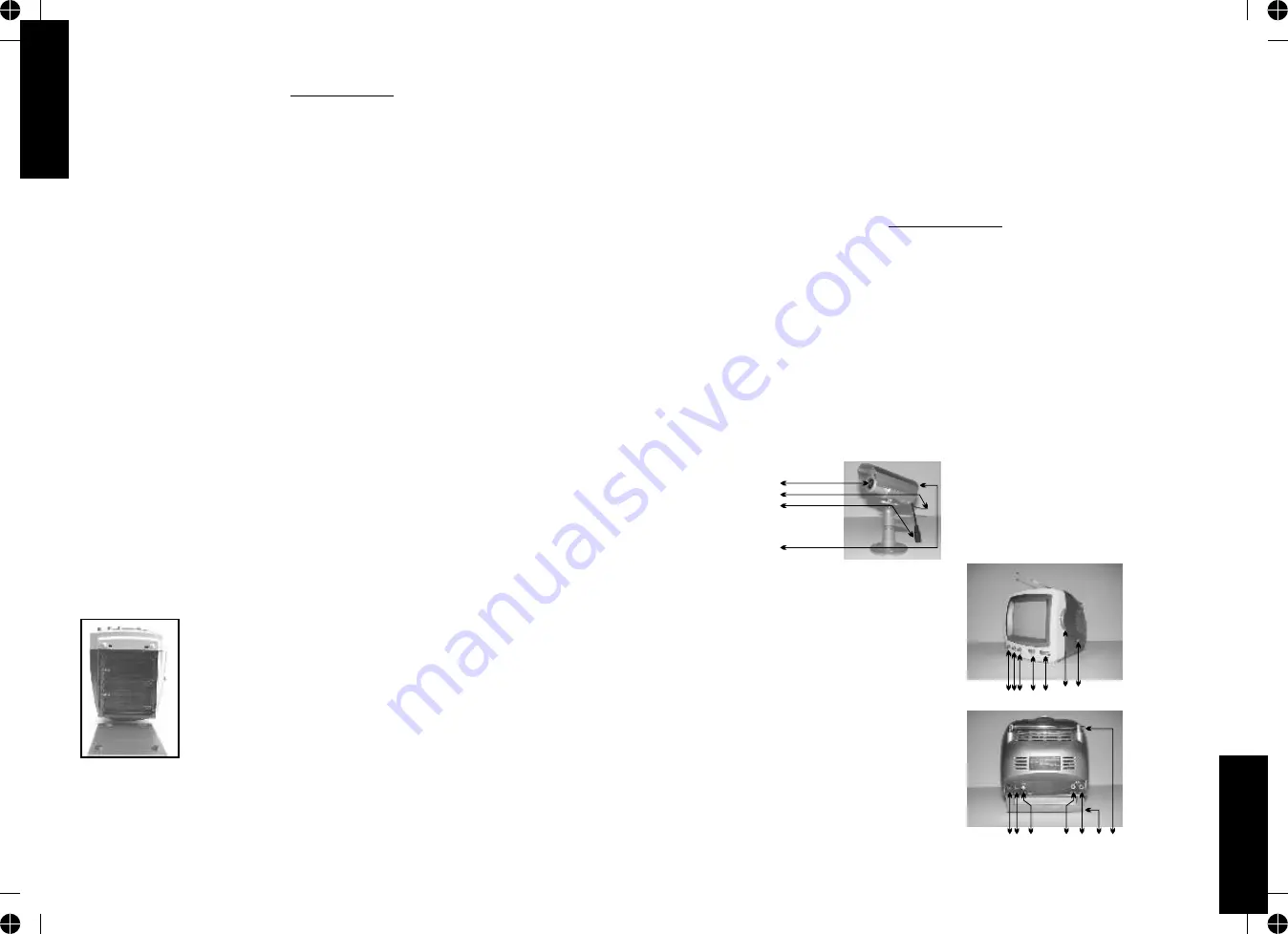
To install/replace batteries:
1. Remove the battery cover by pushing the lock area marked “OPEN”.
2. Insert (or remove) 10 C size batteries.
!!!NOTE!!!
:
Install batteries using the polarity markings (+ and-) on the battery chassis.
E4.
D3.
LÜFTUNG
Schlitze und Öffnungen im Gehäuse und auf der Rückseite oder im Boden sorgen für die erforderliche
Lüftung und sichern die Funktionsfähigkeit des Monitors oder der Ausrüstung und schützen diese vor
Überhitzung. Diese Öffnungen dürfen nicht versperrt oder abgedeckt werden. Die Öffnungen dürfen
nicht versperrt werden, in dem der Monitor auf ein(en) Bett, Sofa, Teppich oder ähnliche Flächen
gestellt wird.. Der Monitor oder die Empfängerausrüstung darf nicht in der Nähe oder über einer
Wärmequelle oder eines(m) Radiator(s) aufgestellt werden. Der Monitor oder die Empfängergeräte
sollten nicht in Einbauschränken oder Regalen untergebracht werden, es sei denn die erforderliche
Lüftung ist dort gewährleistet.
LIEFERUMFANG
- Kamera mit eingebautem Sender
- 13.5 V AC/DC Adapter für den Monitor
- Schwarz-weiß 5.5 Zoll Monitor mit eingebautem 2.4 GHz Empfänger
- 5V AC/DC Adapter für die Kamera
- Kamera Halterung
!!! ACHTUNG !!!
Dieses System enthält zwei AC/DC Adapter mit unterschiedlichen Voltspannungen. Verwenden Sie
den Adapter mit dem Aufkleber OUTPUT: 5V DC nur für die Kamera. Der Adapter mit dem Aufkleber
OUTPUT: 13.5V DC ist ausschließlich für den Monitor bestimmt. Die AC/DC Adapter sind nicht
untereinander austauschbar.
ELEMENTE DES DRAHTLOSEN ÜBERWACHUNGSSYSTEMS
Teile der Kamera
1. Kameralinse
2. Antenne
3. 5V DC Eingangsbuchse
4. Kanalwahlschalter (auf der Rückseite)
Teile des Monitors
Vorderseite
1. Helligkeitsregler
2. Kontrastregler
3. Vertikaler Bildfangregler (V-Hold)
4. Kanalwahl
5. Lautstärkenregler / Power ON/OFF
6. TV Kanaleinstellung
7. TV Bandwahl VL / VH UHF
Rückseite
8. 13.5V DC Strom Eingangsbuchse
9. ANT Buchse
10. AV/TV Schalter
11. Audio Ausgangsbuchse
12. Video Ausgangsbuchse
13. Batteriegehäuse (10 C-Batterien)
14. Teleskop Antenne
1.
2.
3.
4.
1
6 7
23 4 5
8
11
9
12 13 14
10


