AP BIO
Technical Description
400/500/1000/2400
FG-DC_10523-GB_AP Bio_IOM-R0-12/2020 • Subject to modifications
13
4.2
Functional description
4.2.1 AP BIO air purifier (Model 2400)
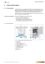
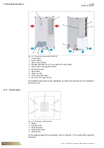
Fig. 4-4
Functional overview
1: Indoor air inlet
2: Control panel
3: Indicator light
4: Fan
5: Air outlets
6: Second HEPA H14 filtration barrier
7: First ISO ePM1 55% (F7) filtration barrier
The control panel (2) used to adjust the air flow rate of the unit.
The electrically driven fan (4) creates a constant negative pressure in the air column.
The air flows through the indoor air inlet (1) and further through the ISO ePM1 55%
(F7) filtration barrier (7). In this step 55% of particles and microbes are captured.
A second HEPA H14 filtration barrier (6), which is also impregnated with the 100%
natural AirFend
TM
bio-decontaminating solution in powder form, deactivates viruses
and bacteria.
The clean air flows out through the air outlets (5) where traps are present to reduce
noise levels.
The indicator light (3) indicates a filter change when the loading conditions are
reached.
Содержание AP BIO 1000
Страница 1: ...AP BIO 400 500 1000 2400 AIR PURIFIER INSTALLATION OPERATION AND MAINTENANCE MANUAL ...
Страница 30: ...Notes AP BIO 400 500 1000 2400 30 FG DC_10523 GB_AP Bio_IOM R0 12 2020 Subject to modifications ...
Страница 31: ...AP BIO Notes 400 500 1000 2400 FG DC_10523 GB_AP Bio_IOM R0 12 2020 Subject to modifications 31 ...


