background image

4-48

4

Service Procedures

2.

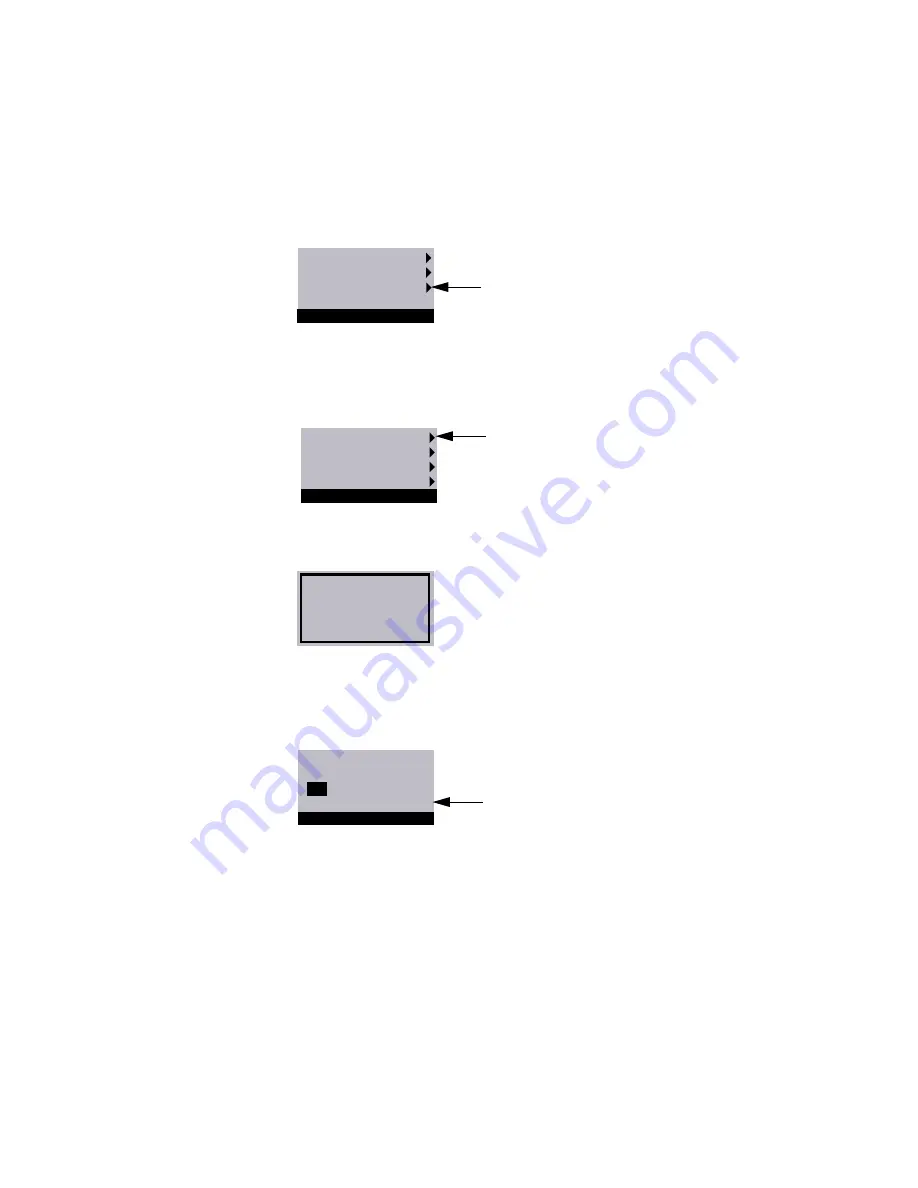
Access the Functions menu and then select Reboot System from the Shut Down menu 
(shown below).

3.

When the diagnostics begin, press the fourth line selection button to access the 
Service menu.

4.

Select Install Software from the Service menu.

5.

At the following screen, press the eject button on the CD-ROM drive and insert the 
language-specific System Software CD.

If an error message appears, verify that the correct System Software CD is inserted.

6.

When the following screen is displayed, make sure “Yes” is displayed and then select 
OK. The installation process will begin immediately.

Wait while the Print Controller X4(AR-PE1) Control Panel displays screens that indicate 
that the software is being installed.

Restart Server
Shut Down System
Reboot System

S

Shut Down

Select

Install Software
Restore Backup
Install Option
Start System

Service 


Select

Insert System 
Software CD and 
press any key.

All data will be
deleted. Continue?

Yes

                  OK

Install Software

Select

Содержание AR-PE1

Страница 1: ...Part Number 45013169 PRINT CONTROLLER X4 AR PE1 INSTA LLA TION AND SER VICE GUIDE for Sharp dig ital ful l col or co p ier s A guide for ser vice technicians ...

Страница 2: ......

Страница 3: ...IMPLIED WARRANTIES IS NOT PERMITTED BY SOME STATES THE ABOVE EXCLUSION MAY NOT APPLY TO YOU IN NO EVENT WILL APPLE ITS DIRECTORS OFFICERS EMPLOYEES OR AGENTS BE LIABLE TO YOU FOR ANY CONSEQUENTIAL INCIDENTAL OR INDIRECT DAMAGES INCLUDING DAMAGES FOR LOSS OF BUSINESS PROFITS BUSINESS INTERRUPTION LOSS OF BUSINESS INFORMATION AND THE LIKE ARISING OUT OF THE USE OR INABILITY TO USE THE APPLE SOFTWARE...

Страница 4: ...Agreement You may not a make use of the Software directly or indirectly to print bitmap images with print resolutions of 600720 dots per inch or greater or to generate fonts or typefaces for use other than with Print Controller X4 AR PE1 b make or have made or permit to be made any copies of the Software Coded Font Programs accompanying documentation or portions thereof except as necessary for use...

Страница 5: ... OR INCIDENTAL DAMAGES THE ABOVE LIMITATION MAY NOT APPLY TO YOU Export Controls You agree that you will not export or re export the Software or Coded Font Programs in any form without the appropriate United States and foreign government licenses Your failure to comply with this provision is a material breach of this Agreement Government Use Use duplication or disclosure of the Software by the Uni...

Страница 6: ......

Страница 7: ...quence 2 1 Checking the customer site 2 3 Setting customer expectations 2 4 Unpacking the Print Controller X4 AR PE1 2 5 Print Controller X4 AR PE1 panels 2 7 Chapter 3 Connecting the Print Controller X4 AR PE1 Preliminary checkout 3 1 Connecting to the copier 3 3 Verifying the connection 3 4 Printing the Print Controller X4 AR PE1 Test Page 3 4 Installing additional options 3 5 Connecting to the ...

Страница 8: ... boards 4 13 AGP video board 4 13 Copier interface board 4 15 IX UIB board 4 17 Ethernet board 4 19 Motherboard 4 21 Removing the Print Controller X4 AR PE1 motherboard 4 22 Replacing the motherboard 4 24 Replacing parts on the motherboard 4 26 Motherboard jumpers 4 31 Fans 4 32 Front panel fan 4 32 CPU fan 4 34 Power supply 4 35 Checking voltages 4 35 Removing and replacing the power supply 4 36 ...

Страница 9: ... unit 5 8 Errors and beep codes during startup diagnostics 5 9 General Print Controller X4 AR PE1 system error conditions 5 12 Checking the entire Print Controller X4 AR PE1 system 5 14 Checking the copier interface 5 14 Checking network connections 5 15 Printing to the Print Controller X4 AR PE1 5 16 Appendix A Specifications Hardware features A 1 Networking and connectivity A 1 User software A 1...

Страница 10: ......

Страница 11: ... unit Chapter 3 Connecting the Print Controller X4 AR PE1 Connect the Print Controller X4 AR PE1 to the copier and the network and verifying that the system is working correctly overview of the Control Panel Chapter 4 Service Procedures Removal and replacement procedures for Print Controller X4 AR PE1 components Chapter 5 Troubleshooting Common problems and their solutions startup error codes NOTE...

Страница 12: ... of the display window The term system software refers to the software installed on the Print Controller X4 AR PE1 hard disk drive References to other Print Controller X4 AR PE1 manuals such as the Configuration Guide are displayed in italics NOTE The note format highlights important messages and additional information The caution icon indicates a need for special care and safety when handling the...

Страница 13: ... down networked devices without the knowledge and express permission of the system or network administrator or the shop supervisor 3 Never enter an IP address in Print Controller X4 AR PE1 Network Setup Only the network administrator should enter an IP address on a network device Assigning the Print Controller X4 AR PE1 an incorrect IP address may cause unpredictable errors on any or all devices c...

Страница 14: ...he cost of a new board When possible work on a ground connected antistatic mat Wear an antistatic grounding strap grounded at the same place as the antistatic mat If that is not possible Attach a grounding strap to your wrist Attach the other end to a good ground When you unpack the Print Controller X4 AR PE1 from the carton for the first time touch a metal area of the copier to discharge the stat...

Страница 15: ...roller X4 AR PE1 you should bring the following tools and parts ESD wrist grounding strap and antistatic mat Wire cutters 2 Phillips head screwdrivers non magnetic Flashlight PROM extractor You should also bring this guide and any technical notes for the Print Controller X4 AR PE1 ...

Страница 16: ......

Страница 17: ...ler X4 AR PE1 with remote user software running on networked PC and Mac OS computers Print files in color grayscale and black and white Use the copier as a high resolution color scanner with Fiery Scan software Use 136 resident PostScript fonts 126 Adobe Type 1 PostScript and 10 TrueType plus two Adobe Multiple Master fonts used for font substitution when printing PDF files Fiery Downloader or any...

Страница 18: ...age data transfer to and from the copier interface board and runs the interpreter The interpreter rasterizes the page description file and then compresses the image pattern into memory using compression technology The interpreter outputs compressed raster data through the image frame buffer memory to the Print Controller X4 AR PE1 copier interface board The copier interface board decompresses the ...

Страница 19: ...n saved in PostScript EPS Encapsulated PostScript or PDF Portable Document Format These files can be downloaded directly to the Print Controller X4 AR PE1 using Fiery Downloader one of the remote utilities for use with the Print Controller X4 AR PE1 Networked computers Motherboard Power supply External Devices Copier Print Controller X4 AR PE1 3 3 5 12V DC AC power CPU Network interface Memory and...

Страница 20: ...ontroller X4 AR PE1 126 Adobe Type 1 and 10 TrueType See the Printing Guide for a complete list of PostScript fonts installed on the Print Controller X4 AR PE1 Fiery Downloader Enables users to print PostScript files Encapsulated PostScript EPS files and Portable Document Format PDF files directly to the Print Controller X4 AR PE1 without opening the application in which they were created Fiery Do...

Страница 21: ... 95 98 and Windows NT 4 0 workstations To use the Command WorkStation see the Job Management Guide Color management files ColorSync and ICM color management files that enable users to maintain consistent color from the original artwork to the colors displayed on the monitor to the printed output Color reference files Reference pages that users can print to view the range of colors available on the...

Страница 22: ......

Страница 23: ...our job as easy as possible Installation problems are easier to avoid and diagnose if you proceed from the component to the system level and verify functionality at each stage Figure 2 1 on page 2 2 outlines the recommended installation procedure for connecting the Print Controller X4 AR PE1 to the copier Because the Print Controller X4 AR PE1 is a node on the customer s computer network make sure...

Страница 24: ...ge page 3 4 Network administrator installs Print Controller X4 AR PE1 user software on networked computers that print to the Print Controller X4 AR PE1 see Getting Started Network administrator connects the Print Controller X4 AR PE1 to the network and verifies the connection see page 3 6 and the Configuration Guide Network administrator configures Setup options see the Configuration Guide Check i...

Страница 25: ...t the copier needs adjustment inform the customer After getting approval complete the copier service needed Power Is there a dedicated grounded electrical outlet near the copier for the Print Controller X4 AR PE1 Locate the grounded electrical outlet that will supply power to the Print Controller X4 AR PE1 You should not run the Print Controller X4 AR PE1 and the copier on the same circuit Use a s...

Страница 26: ...onnectivity Equipment downtime and impact on the network can be minimized if the network administrator installs a network connector for the Print Controller X4 AR PE1 and confirms network functionality with the connector in place before the date scheduled for the Print Controller X4 AR PE1 installation The network administrator should have a networked computer available during the installation The...

Страница 27: ...on and software 3 Give the media package to the customer or the network administrator Let the customer or network administrator know that in order to take full advantage of the Print Controller X4 AR PE1 the user software must be installed on computers that will print to the Print Controller X4 AR PE1 4 Set aside the remaining components from the top container 5 Remove the top container and any pa...

Страница 28: ... for Installation FIGURE 2 2 Contents of Print Controller X4 AR PE1 shipping box Print Controller X4 AR PE1 Power cable UK version Media Package Power cable US version Power cable EU version Power cable Japan version ...

Страница 29: ...oor and then open the doors FIGURE 2 3 Front and back panels Back panel Front panel Up button Down button Menu button Drive door Ethernet RJ 45 connector Power switch Power connector Serial connector not used USB connectors not used Parallel connector not used Serial connector not used Monitor option Line selection buttons Activity light Copier interface connector Parallel connector not used CD RO...

Страница 30: ......

Страница 31: ...ller X4 AR PE1 power switch is in the off position press 0 and then connect the other end of the Print Controller X4 AR PE1 power cable to a wall outlet FIGURE 3 1 Print Controller X4 AR PE1 power 2 Power on the Print Controller X4 AR PE1 using the switch at the back of the Print Controller X4 AR PE1 The power supply automatically senses the correct voltage 3 To confirm that the Print Controller X...

Страница 32: ... Check power and cable may display in the Control Panel during the startup process Once the Print Controller X4 AR PE1 is connected to the copier the message should no longer be displayed Before the system reaches the Idle screen it creates a backup of the system software configuration for the language you selected If at some point you need to restore the default configuration of the system softwa...

Страница 33: ...1 and the copier You may need to get permission from the network administrator or supervisor to power off the copier 2 Locate the Print Controller X4 AR PE1 copier interface cable shipped with the copier and connect the cable to the interface port on the copier 3 Connect the other end of the cable to the Print Controller X4 AR PE1 copier interface connector in slot 3 on the back panel see Figure 3...

Страница 34: ... A TEST PAGE FROM THE CONTROL PANEL 1 Power on the copier and allow it to warm up 2 Power on the Print Controller X4 AR PE1 from the power switch on the back panel Messages appear on the Control Panel as the Print Controller X4 AR PE1 runs through its startup diagnostics 3 Before proceeding make sure that the copier is not in use The Print Controller X4 AR PE1 Info screen should read Idle 4 At the...

Страница 35: ...nt engine is functional and that the connection between the Print Controller X4 AR PE1 and the copier is good Installing additional options If the customer has purchased additional Print Controller X4 AR PE1 options install those before connecting the Print Controller X4 AR PE1 to the network For installation instructions see the documentation included in each option kit NOTE After installing opti...

Страница 36: ...t for more information FIGURE 3 3 Network connectors on the back panel TO CONNECT A TWISTED PAIR CABLE TO THE PRINT CONTROLLER X4 AR PE1 1 Power off the Print Controller X4 AR PE1 before connecting it to any network device If the system has just finished processing wait 5 seconds after the system reaches the idle state before using the power switch to power off the unit 2 Connect the network cable...

Страница 37: ...ection Once the network connection has been made and the Print Controller X4 AR PE1 has the correct Setup configuration the Print Controller X4 AR PE1 should be available on the network The network administrator should perform any additional network setup verify the network connection verify that the Print Controller X4 AR PE1 appears in the list of printers and print a few test documents from a n...

Страница 38: ... X4 AR PE1 The current status of the Print Controller X4 AR PE1 and Setup information are displayed in the Print Controller X4 AR PE1 display window Print Controller X4 AR PE1 activity can be monitored in the display window and functions of the Print Controller X4 AR PE1 such as printing a Test Page and installing or updating system software can be controlled using the buttons on the Control Panel...

Страница 39: ...1 is powered off Line selection buttons There are four line selection buttons on the right side of the Control Panel Use these buttons to select the command displayed on the corresponding line of the display window A special character appears in the display window next to a button when it is available Up and down buttons Use these buttons to scroll to different screens in multi screen lists to sel...

Страница 40: ...n displays the name of the current screen with the icon for that screen highlighted Icons for other active screens are also displayed but are not highlighted The Print Controller X4 AR PE1 screens display the following information FIGURE 3 5 Control Panel screens during printing If an error occurs the Alert screen is displayed with a message describing the error Cancel Job Jane D Copies 1 100 Prin...

Страница 41: ...ho sent the job that is currently being processed Copies Total The number of copies of the current page that have been printed so far and the total number of copies of this page that were requested RIP Status When the Print Controller X4 AR PE1 is processing a job the RIP Status screen is activated This screen displays the following Cancel Job Press the top line selection button to cancel the job ...

Страница 42: ...or Printing Number of MB The space in megabytes available on the Print Controller X4 AR PE1 hard disk Version The system software version running on the Print Controller X4 AR PE1 Functions The Functions screen also is always active but it appears in the display window only when the user has pressed the Menu button to select it Use the up and down buttons to scroll through the list of menu command...

Страница 43: ...ncludes information about all current Setup settings calibration profile and the Ethernet address of the Print Controller X4 AR PE1 The Configuration Page also provides version information for the BIOS chip and information on any options installed on the Print Controller X4 AR PE1 Job Log Prints the log of the last 55 jobs by default For more information about the job log see the Printing Guide Co...

Страница 44: ...rom the server queues It also clears the Job Log all jobs saved on the server hard disk drive and the index of all archived jobs Run Setup allows you to access the Setup options in order to configure the network and printing environment Typically it is the network administrator s responsibility to configure Setup according to the network and user environment Setup is required the first time the co...

Страница 45: ...nfo screen when the Print Controller X4 AR PE1 is finished processing the job 2 At the Idle screen press the menu button once to display the Functions menu 3 Select Shut Down from the Functions menu At the next screen select Shut Down System The message It is now safe to power off the system is displayed 4 Power off the Print Controller X4 AR PE1 using the power switch on the back panel TO RESTART...

Страница 46: ......

Страница 47: ... your authorized service representative When performing the service procedures described in this chapter follow the precautions listed in Precautions on page vii NOTE The tools required for service are listed in Tools you will need on page ix System software service Print Controller X4 AR PE1 system software is installed on the HDD at the factory A backup of the system software resides on a separa...

Страница 48: ...rive 5 ZIP drive 6 ZIP drive cable 7 Power button cable 8 Reset cable 9 Drive bracket 10 Speaker cable 11 Tray 12 Front panel fan and fan cable 13 Front panel fan housing 14 HDD 15 HDD bracket 16 Power supply 17 Power supply cable 18 Motherboard 19 CPU fan heatsink and CPU fan cable 20 Ethernet board 21 UIB cable to IX UIB board 22 IX UIB board 23 Copier interface board 24 AGP video board 25 Side ...

Страница 49: ...Power off the Print Controller X4 AR PE1 when changing the copier s toner in order to prevent the fan from drawing toner into the Print Controller X4 AR PE1 TO SHUT DOWN THE PRINT CONTROLLER X4 AR PE1 1 Make sure that the Print Controller X4 AR PE1 Info screen reads Idle When Printing or Ripping appears on the Control Panel the Print Controller X4 AR PE1 is currently processing Idle appears in the...

Страница 50: ...gently pull it away from the tray 4 Lift off the side panel FIGURE 4 2 Removing the Print Controller X4 AR PE1 side panel 5 The Print Controller X4 AR PE1 internal components are now accessible Attach an ESD wrist strap before handling internal parts The Print Controller X4 AR PE1 is shipped from the factory with a standard board configuration as shown in Figure 4 3 If optional components have bee...

Страница 51: ...nts inside the tray are facing up FIGURE 4 3 Print Controller X4 AR PE1 side view and back panel view Motherboard connectors AGP1 AGP video board PCI1 Empty PCI2 Copier interface board PCI3 IX UIB board PCI4 Empty optional Token Ring board PCI5 Ethernet board ISA1 Empty ISA2 Empty Back panel view Side view AGP1 PCI1 PCI2 PCI3 PCI4 PCI5 ISA1 ISA2 Slot 1 Slot 2 Slot 3 Slot 4 Slot 5 Slot 6 Slot 7 ...

Страница 52: ... REMOVE THE FRONT PANEL 1 Make sure you have powered off the Print Controller X4 AR PE1 and removed all the cables from the back 2 Remove the side panel as described in To open the Print Controller X4 AR PE1 on page 4 4 3 Grasp the front panel and gently detach it from the tray Do not pull the front panel away from the tray as the UIB cable is still connected to the front panel FIGURE 4 4 Front pa...

Страница 53: ...ont panel and should not be removed FIGURE 4 5 Removing the front panel TO REPLACE THE FRONT PANEL 1 Connect the UIB cable to its connector on the tray and then replace the screws The other end of the cable should be attached to the front panel 2 Replace the front panel as described in To reassemble the Print Controller X4 AR PE1 on page 4 11 3 Align the front panel with the front of the tray and ...

Страница 54: ...own firmly on each board to make sure it is securely installed Looking into the tray from the top the standard board configuration includes the following from top to bottom Connector AGP1 AGP video board Connector PCI1 Empty Connector PCI2 Copier interface board Connector PCI3 IX UIB board Connector PCI4 Empty optional Token Ring board Connector PCI5 Ethernet board Connector ISA1 Empty Connector I...

Страница 55: ...connector PIDE a HDD IDE master b CD ROM drive IDE slave 3 CPU fan cable CPU fan Motherboard connector CPU FAN 4 ZIP drive cable Motherboard connector SIDE ZIP drive 5 UIB cable UIB in the front panel Connector J4 on the IX UIB board 6 Reset button cable Motherboard pins RST Reset button pad on the front of the tray 7 Front panel fan cable Front panel fan Fan connector on the motherboard CFAN 8 Po...

Страница 56: ... on the levers on each side of the DIMM FIGURE 4 7 Releasing the DIMM levers 3 Slide the DIMM straight out of the socket 4 To replace a DIMM gently slide the DIMM straight into the socket until the levers at each side lock into place Make sure that the levers close securely around the ends of the DIMM and that each DIMM is fully seated in its socket If you removed the DIMMs completely note that DI...

Страница 57: ...t Controller X4 AR PE1 in its standard operating position Place the side panel onto the Print Controller X4 AR PE1 so the grooves on the bottom of the side panel fit into the grooves in the tray see Figure 4 8 Be careful not to damage any ribbon cables if necessary fold the ribbon cables inside the tray before replacing the side panel 3 Close the side panel Two clips on the top edge of the panel w...

Страница 58: ...it see To replace the front panel on page 4 7 6 Connect any cables removed during service to the back of the Print Controller X4 AR PE1 7 Before you leave the customer site verify Print Controller X4 AR PE1 operation as outlined in Figure 4 9 FIGURE 4 9 Print Controller X4 AR PE1 connection verification steps Connect the Print Controller X4 AR PE1 to the network See page 3 6 and the Configuration ...

Страница 59: ...tion instructions provided with that board AGP video board The AGP Accelerated Graphics Port video board installed in the Print Controller X4 AR PE1 provides connectivity to an optional monitor which connects to the 15 pin D connector occupying slot 1 on the back of the Print Controller X4 AR PE1 tray on the AGP board The other connector on the board connects to motherboard connector AGP1 FIGURE 4...

Страница 60: ... TO REPLACE THE AGP VIDEO BOARD 1 Reseat the AGP video board in motherboard connector AGP1 The component side of the board should be facing down towards the bottom of the tray When replacing the AGP video board slide it straight into the board guides As you plug the board into AGP1 make sure that the board connectors are properly aligned with the motherboard connector The board connector is keyed ...

Страница 61: ...Controller X4 AR PE1 and the copier The board is installed in connector PCI2 on the motherboard The copier interface connector on one side of the board occupies slot 3 on the back panel of the Print Controller X4 AR PE1 and connects to the copier interface cable FIGURE 4 11 Diagram of copier interface board component side To motherboard connector PCI2 Copier interface connector ...

Страница 62: ...istatic bag TO REPLACE THE COPIER INTERFACE BOARD 1 Reseat the copier interface board in motherboard connector PCI2 The component side of the copier interface board should be facing down towards the bottom of the tray When replacing the copier interface board slide it straight into the board guides As you plug the board into PCI2 make sure that the board connectors are properly aligned with the mo...

Страница 63: ...therboard connector PCI3 provides the interface between the LCD in the front panel and the motherboard The UIB cable from the front panel attaches to connector J4 on the IX UIB board FIGURE 4 12 IX UIB board Parallel port not used To motherboard connector PCI3 UIB cable connector J4 ...

Страница 64: ... in connector PCI3 on the motherboard Make sure that the parallel connector on the board extends through slot 4 in the back panel The component side of the IX UIB board should be facing the bottom of the tray When replacing the IX UIB board slide it straight into the board guides As you plug the board into PCI3 make sure that the board connectors are properly aligned with the motherboard connector...

Страница 65: ... the Print Controller X4 AR PE1 and the customer s network The Ethernet board has one RJ 45 network connector for a 10 100BaseT unshielded twisted pair cable The Ethernet board is installed in motherboard connector PCI5 FIGURE 4 13 Ethernet board connectors RJ 45 connector To motherboard connector PCI5 ...

Страница 66: ...Insert the Ethernet board into motherboard connector PCI5 The component side of the board should be facing down towards the bottom of the tray When replacing the Ethernet board slide it straight into the board guides As you plug the board into PCI5 make sure that the board connectors are properly aligned with the motherboard connector The board connector is keyed to fit only one way on the motherb...

Страница 67: ...8 22 i Key 1 Optional keyboard mouse connectors 2 USB connector not used 3 433MHz CPU heatsink and CPU fan 4 AGP video board connector AGP1 5 Empty PCI1 6 Copier interface board connector PCI2 7 IX UIB board connector PCI3 8 Option board connector PCI4 9 Ethernet board connector PCI5 10 Empty ISA1 11 Empty ISA2 12 BIOS chip U8 13 Speaker cable pins SPKR 14 Front panel fan cable connector CFAN 15 R...

Страница 68: ...handling the Print Controller X4 AR PE1 boards TO REMOVE BOARDS FROM THE MOTHERBOARD 1 Power off the Print Controller X4 AR PE1 and remove the side panel as described on page 4 4 2 Remove the board mounting bracket screws for boards occupying back panel slots 3 Remove the following boards from the motherboard and place each board on an antistatic surface AGP board in connector AGP1 Copier interfac...

Страница 69: ...rom pins RST 7 Remove the speaker cables from pins SPKR TO REMOVE THE MOTHERBOARD 1 If you are replacing the motherboard remove the following from the motherboard Memory see page 4 26 CPU heatsink and CPU fan see page 4 28 BIOS chip see page 4 29 2 Using a 2 Phillips head screw driver remove the six motherboard mounting screws 3 Gently slide the motherboard out of the back panel cutouts Make sure ...

Страница 70: ...ing screws that attach the motherboard to the tray 4 If you replaced the motherboard with a new board replace the following components on the board Memory see page 4 26 CPU heatsink and CPU fan see page 4 28 BIOS chip see page 4 29 TO REPLACE BOARDS 1 Replace the following boards in the motherboard AGP video board in connector AGP1 Copier interface board in connector PCI2 IX UIB board in connector...

Страница 71: ...motherboard insert the BIOS chip with the socket mount from the motherboard you removed into the BIOS socket on the replacement board 2 Attach the board mounting bracket screws for boards installed in back panel slots NOTE Make sure unused slots have slot covers installed Uncovered slots reduce air flow and could cause the Print Controller X4 AR PE1 to overheat 3 Press down on each cable connector...

Страница 72: ...e Print Controller X4 AR PE1 as described in To shut down the Print Controller X4 AR PE1 on page 4 3 and remove the side panel as described in To open the Print Controller X4 AR PE1 on page 4 4 DIMMs The Print Controller X4 AR PE1 motherboard has three DIMM sockets DIMM1 DIMM2 DIMM3 with 192MB installed Approved DIMMs are available from your service representative FIGURE 4 15 Motherboard DIMM sock...

Страница 73: ...vers on each side lock into place Make sure that the levers close securely around the ends of the DIMM and that each DIMM is fully seated in its socket NOTE DIMMs fit the socket only one way The two notches on the bottom of each DIMM should line up with the notches in the socket 4 Reassemble the Print Controller X4 AR PE1 and verify its functionality see Restoring Print Controller X4 AR PE1 functi...

Страница 74: ...sink on page 4 34 2 Lift the lever to release the CPU from the socket see Figure 4 17 FIGURE 4 17 Removing the CPU 3 Grasp the edges of the CPU and gently pull it out of the socket 4 Insert the new CPU so that the notch on the chip lines up with the notch area on the socket Pin 1 on the CPU is denoted by an angled corner The angled corner should point to the small 1 printed on the board directly b...

Страница 75: ...X4 AR PE1 functionality after service on page 4 11 Motherboard battery The battery on the motherboard is located at BT1 To replace it use a 3V manganese dioxide lithium coin cell battery Panasonic CR2032 or equivalent CAUTION There is danger of explosion if the battery is replaced with the incorrect type Replace only with the same type recommended by the manufacturer Dispose of used batteries acco...

Страница 76: ...ry slide the battery into the socket under the clip with the positive side facing up Make sure the clip holds the battery securely in the socket 5 Reassemble the Print Controller X4 AR PE1 and verify its functionality as described on page 4 11 NOTE When you power on the Print Controller X4 AR PE1 let the Start up diagnostics complete then power off and on again to reinitialize the realtime clock 6...

Страница 77: ...umper installed on pins 1 and 2 during normal operation To reset the CMOS to the BIOS defaults move the jumper to pins 2 and 3 reboot and then replace jumper to pins 1 and 2 JP10 CPU speed settings Jumper installed on pins 1 and 2 This setting should not be changed JP11 CPU speed settings Jumper installed on pins 1 and 2 This setting should not be changed JP12 CPU speed settings Jumper installed o...

Страница 78: ... a fan error message is displayed on the Control Panel the most likely problem is a faulty power connection see To check board and cable connections on page 4 8 Front panel fan The following steps describe the procedure required in order to replace the fan installed on the front panel of the Print Controller X4 AR PE1 The fan is held in the tray with clips The front panel fan cable attaches to mot...

Страница 79: ...ing FIGURE 4 21 Removing the fan from the housing TO REPLACE THE FRONT PANEL FAN 1 Insert the new fan into the fan housing and then press the fan cable into place in the fan housing An arrow on the side of the fan indicates the airflow direction Make sure the fan is positioned so that the arrow points toward the interior of the chassis 2 Align the fan housing clips with the holes in the front pane...

Страница 80: ...oard connector CPU FAN 2 Press down and hold the clip at the top of the CPU fan 3 Lift the fan and heatsink assembly away from the CPU TO REPLACE THE CPU FAN 1 Align the CPU fan with the heatsink and then press the assembly onto the motherboard 2 Reattach the CPU fan cable to motherboard connector CPU FAN 3 Reassemble the Print Controller X4 AR PE1 and verify its functionality see Restoring Print ...

Страница 81: ...ector for future options Test voltages on the cable connectors on the power supply not on the board or component connectors Table 4 1 describes the Print Controller X4 AR PE1 power connectors TABLE 4 1 Print Controller X4 AR PE1 power connectors Connector Pins Color Voltage 1 2 11 Green 3 3V 3 5 7 13 15 16 17 Black common 18 White 5V not connected 4 6 19 20 Red 5V 10 Yellow 12V 12 Blue 12V 14 not ...

Страница 82: ...m its connectors on the motherboard ZIP drive HDD and CD ROM drive 3 Remove the four screws on the back panel of the Print Controller X4 AR PE1 that attach the power supply to the tray see Figure 4 23 on page 4 37 NOTE Be sure to hold the power supply while you remove the screws 4 Remove the power supply 1 Yellow 12V 2 Black common 3 Black common 4 Red 5V 1 Yellow 12V 2 Black common 3 Black common...

Страница 83: ... to the motherboard power connector PWR CON Large 4 pin power cable to the power connector on the ZIP drive Large 4 pin power cable to the power connector on the CD ROM drive Large 4 pin power cable to the power connector on the HDD 4 Reassemble the Print Controller X4 AR PE1 and verify its functionality see Restoring Print Controller X4 AR PE1 functionality after service on page 4 11 If you cut a...

Страница 84: ...splayed on the Control Panel The HDD is installed in the bracket in the front of the tray FIGURE 4 24 Print Controller X4 AR PE1 HDD hard disk drive If you are replacing the HDD you will need The appropriate Print Controller X4 AR PE1 system software including documentation for the Print Controller X4 AR PE1 you are servicing Compatible version of the user software for networked computers that wil...

Страница 85: ...the HDD is replaced 2 Power off and open the Print Controller X4 AR PE1 as described in To shut down the Print Controller X4 AR PE1 on page 4 3 and To open the Print Controller X4 AR PE1 on page 4 4 3 Remove the IDE cable from the CD ROM drive and the HDD 4 Remove the mounting screw on the top of the HDD bracket see Figure 4 24 on page 4 38 5 Push down and hold the thumb clip on the top of the HDD...

Страница 86: ...r NOTE Make sure that the connector on the HDD is below the bracket mounting hole 3 Align the guides on the top of the HDD bracket with the rails in the mounting hardware in the tray and then slide the bracket into the hardware The thumb clip will click into place when the drive is installed correctly 4 Once the HDD bracket is securely installed in the mounting hardware in the tray insert the moun...

Страница 87: ...R PE1 as described in To shut down the Print Controller X4 AR PE1 on page 4 3 2 Remove the front panel as described in To remove the front panel on page 4 6 3 Remove the IDE cable connected to the back of the CD ROM drive 4 Remove the power supply cable connected to the CD ROM drive 5 Cut any tie wraps that hold the power supply cable to the drive bracket 6 Squeeze and hold the thumb clips on the ...

Страница 88: ...rive into the bottom large slot in the tray and push it in until the thumb clips click into place Make sure the IDE setting for the CD ROM drive is set to slave 3 Replace any tie wraps that you removed earlier 4 Connect the power supply cable to its connector on the back of the CD ROM drive 5 Connect the IDE cable to its connector on the back of the drive 6 Reassemble the Print Controller X4 AR PE...

Страница 89: ...d To open the Print Controller X4 AR PE1 on page 4 4 2 Remove the front panel as described in Removing the front panel on page 4 6 3 Remove the ZIP drive cable connected to the back of the ZIP drive 4 Remove the power supply cable connected to the ZIP drive Cut any tie wraps that hold the power supply cable to the ZIP drive bracket 5 Squeeze and hold the thumb clips on the sides of the ZIP drive a...

Страница 90: ...ide the drive into the top small mounting bracket in the front of the tray and push it in the slot until the thumb clips click into place 3 Connect the ZIP drive cable to its connector on the back of the ZIP drive 4 Connect the power supply cable to its connector on the back of the ZIP drive 5 Replace any tie wraps that you removed earlier 6 Reassemble the Print Controller X4 AR PE1 see Restoring ...

Страница 91: ...r X4 AR PE1 HDD are deleted Resident fonts are restored during system software installation If any additional fonts were downloaded to the Print Controller X4 AR PE1 the network administrator can reinstall the fonts using Fiery Downloader To determine which additional fonts were downloaded to the Print Controller X4 AR PE1 print the Font List before you install or restore the system software and a...

Страница 92: ...tomer s current Setup configuration The Setup configuration will be reset to the default configuration when backup system software is restored Font List the Font List details the fonts that are resident on the Print Controller X4 AR PE1 HDD Along with the fonts provided the customer may have installed additional fonts that will be deleted when the backup system software is restored 2 Access the Fu...

Страница 93: ...ulations that may have been deleted due to system software restoration Installing system software from a CD The Print Controller X4 AR PE1 System Software CD includes the system software and fonts Use the System Software CD when You replace the Print Controller X4 AR PE1 HDD You upgrade to a more recent version of the system software Restore Backup fails TO INSTALL PRINT CONTROLLER X4 AR PE1 SYSTE...

Страница 94: ... an error message appears verify that the correct System Software CD is inserted 6 When the following screen is displayed make sure Yes is displayed and then select OK The installation process will begin immediately Wait while the Print Controller X4 AR PE1 Control Panel displays screens that indicate that the software is being installed Restart Server Shut Down System Reboot System SShut Down Sel...

Страница 95: ...nt Controller X4 AR PE1 will initialize the system and will also run diagnostics and create a system backup 8 Configure Setup using the Configuration page you printed earlier Bypass settings not included on the Configuration page if it is more appropriate for the network administrator to set them See the Configuration Guide for more information 9 Reinstall fonts Command WorkStation software or cus...

Страница 96: ......

Страница 97: ...n page 5 14 Try a phone check before you go to the customer site Before you go to the customer site on page 5 3 suggests areas you should check out before making a call to the customer site With a phone call you can find out if the problem is a simple operating failure or a failure caused by a network or configuration change You can ask the customer to check for loose cables on the back of the Pri...

Страница 98: ...erally part of a configuration like the one shown below and in Figure 5 2 on page 5 3 Problems may occur in one of three areas Inside the Print Controller X4 AR PE1 In the interface between the Print Controller X4 AR PE1 and the copier In the interface between the Print Controller X4 AR PE1 and the workstations or computers to which it is connected FIGURE 5 1 Troubleshooting the system This chapte...

Страница 99: ... Control Panel on the Print Controller X4 AR PE1 for an error message If the Print Controller X4 AR PE1 Control Panel reports an error the customer can check the copier interface cable connections between the Print Controller X4 AR PE1 and the copier Networked computers Motherboard Power supply External Devices Copier Print Controller X4 AR PE1 3 3 5 12V DC AC power CPU Network interface Memory an...

Страница 100: ...Keep a log of the failures and messages the customer has observed 3 Has the customer made any network changes If so request that the customer s network administrator verify the Print Controller X4 AR PE1 network requirements See Checking network connections on page 5 15 4 Has the customer added or removed any equipment that might impact the operation of the Print Controller X4 AR PE1 If so obtain ...

Страница 101: ... proper connectors on the back panel of the Print Controller X4 AR PE1 see Figure 5 3 The power cable is plugged into the wall supply The power switch on the back panel of the Print Controller X4 AR PE1 is powered on FIGURE 5 3 Back panel of Print Controller X4 AR PE1 If all the connectors are properly in place and the power is on proceed to the next stage of troubleshooting Parallel connector not...

Страница 102: ... page 4 4 and To remove the front panel on page 4 6 3 Before you touch any components inside the Print Controller X4 AR PE1 attach a grounding strap to your wrist and discharge any static electricity on your body by touching the metal cover of the Print Controller X4 AR PE1 4 Inspect the inside of the Print Controller X4 AR PE1 For details see Checking Print Controller X4 AR PE1 internal connectio...

Страница 103: ...ROM drive 5 ZIP drive 6 ZIP drive cable 7 Power button cable 8 Reset cable 9 Drive bracket 10 Speaker cable 11 Tray 12 Front panel fan and fan cable 13 Front panel fan housing 14 HDD 15 HDD bracket 16 Power supply 17 Power supply cable 18 Motherboard 19 CPU fan heatsink and CPU fan cable 20 Ethernet board 21 UIB cable to IX UIB board 22 IX UIB board 23 Copier interface board 24 AGP video board 25 ...

Страница 104: ... the Configuration Guide for details TO ISOLATE THE PRINT CONTROLLER X4 AR PE1 1 Isolate the Print Controller X4 AR PE1 from the copier and from the network by disconnecting the following cables from their connectors on the back panel of the Print Controller X4 AR PE1 Network connector Copier interface connector 2 Make sure the power cable to the Print Controller X4 AR PE1 is still in place 3 Powe...

Страница 105: ...he system cannot display the startup diagnostic screen the Print Controller X4 AR PE1 will indicate an error with beep codes and a flashing or solid red activity light NOTE During startup the diagnostics check the activity light to make sure it is functional The activity light on the Print Controller X4 AR PE1 Control Panel flashed red briefly during this time even though no errors have occurred W...

Страница 106: ...faulty DIMM s If the above does not correct the error you may need to replace the motherboard 6 short beeps pause 1 long beep 8 short beeps pause 1 long beep CMOS settings Reboot the Print Controller X4 AR PE1 If the problem persists replace the battery on the motherboard If the problem still persists you may need to replace the motherboard NOTE If you replace the battery reset the time and date i...

Страница 107: ...d CMOS Memory Size Mismatch Reboot the Print Controller X4 AR PE1 If the problem persists replace the battery on the motherboard If the problem still persists you may need to replace the motherboard NOTE Reset the time and date in Setup after replacing the battery Cache Memory Error Replace the motherboard Hard Disk Error Check IDE cable connections to the HDD and the CD ROM drive If the problem p...

Страница 108: ...ons are faulty or disconnected Check power supply cable connections to the motherboard CD ROM drive CPU fan HDD and ZIP drive Check all cable connections and board connections Power supply has failed Replace the power supply No fan sound but the Print Controller X4 AR PE1 starts up properly Problem with the front panel fan Check the front panel fan cable connection to motherboard connector CFAN If...

Страница 109: ...rsists install system software from the CD Cable connections to the HDD are loose or faulty Check cable connections to the HDD If the problem persists you may need to replace the IDE cable or the HDD Startup diagnostics continue to run HDD is not installed properly Check cable connections to the HDD If the problem persists you may need to replace the HDD Check power cable appears in the Print Cont...

Страница 110: ...ct it to the network See Connecting to the copier on page 3 3 Printing the Print Controller X4 AR PE1 Test Page Before connecting the Print Controller X4 AR PE1 to the network print the Test Page to verify that the Print Controller X4 AR PE1 is connected properly to the copier The Test Page is a color file that resides on the Print Controller X4 AR PE1 hard disk drive TO PRINT A TEST PAGE FROM THE...

Страница 111: ...ion or printing a particular file Most of these problems show up as printing problems and do not necessarily indicate a Print Controller X4 AR PE1 malfunction The customer s network administrator can eliminate many printing problems without requiring you to make a service call The network administrator deals with Copier error conditions Network connection problems that result in the Print Controll...

Страница 112: ...in the Printing Guide Confirmed that the applicable network settings in Setup such as AppleTalk zone IP address Subnet mask and Gateway address match the settings used in the network When you make a service call check the back panel of the Print Controller X4 AR PE1 to make sure that the appropriate network connections are in place Intermittent print quality and color quality problems are difficul...

Страница 113: ... Ring board User software A complete description of Print Controller X4 AR PE1 user software is provided in the Printing Guide For optimal Print Controller X4 AR PE1 performance current versions of the user software should be maintained on every network computer that might print to the Print Controller X4 AR PE1 Safety and emissions compliance The Print Controller X4 AR PE1 has been certified to m...

Страница 114: ......

Страница 115: ...illustrations below to locate a particular component Spare parts overview Part EFI part number Additional page references Power supply 45010451 Page 4 35 Power cable 10015459 Page 3 1 Internal IDE CD ROM drive 45008210 Page 4 41 Internal ZIP drive 45008212 Page 4 43 8 4GB IDE hard disk drive 45008936 Page 4 38 Appendix B Parts List ...

Страница 116: ...List Front panel fan 45010540 Page 4 32 64MB DIMM 45005706 Page 4 26 128MB DIMM 45008230 Page 4 26 Motherboard 45011253 Page 4 21 AGP video board 45008200 Page 4 13 Part EFI part number Additional page references ...

Страница 117: ...rd 45010994 Page 4 15 Token Ring board 45008202 See Using the Token Ring kit for information IX UIB board 45008198 Page 4 17 10 100BaseT Ethernet board 45010938 Page 4 19 Front panel 45010995 Page 4 6 Part EFI part number Additional page references ...

Страница 118: ...38 Page 4 38 and Page 4 41 ZIP drive cable 45008226 Page 4 43 UIB cable 45010537 Page 4 17 Base BIOS chip 45008481 Page 4 29 433MHz CPU 45010435 Page 4 28 Magnetic Optical drive 45010991 Part EFI part number Additional page references ...

Страница 119: ...5 buttons down 2 7 3 8 3 9 line selection 2 7 3 9 menu 2 7 3 8 3 9 power not used 2 7 reset 2 7 troubleshooting 5 12 up 2 7 3 8 3 9 C cables category 5 3 6 checking 5 5 copier interface 2 6 3 3 CPU fan 4 2 4 9 4 34 5 7 front panel fan 4 9 4 33 IDE 4 2 4 9 4 39 4 41 5 7 power 2 5 2 6 power button 4 9 power supply 4 2 4 9 5 7 reseating 4 8 reset button 4 9 UIB 4 2 4 7 4 9 5 7 UTP 3 6 ZIP drive 4 2 5...

Страница 120: ... 3 connector 3 3 4 5 CPU 1 2 4 28 fan 4 2 4 34 5 7 fan cable 4 2 4 9 4 34 5 7 heatsink 4 34 jumper setting 4 31 customer site checklist 2 3 D damage reporting vii 2 5 diagnostics beep codes 5 10 copier interface 5 14 Ethernet address 5 15 Run Diagnostics option 3 14 startup 5 11 startup errors 5 9 startup screen 5 9 Test I F Board 3 14 Test Page 3 4 5 14 DIMMs banks 4 26 configurations 1 2 4 26 re...

Страница 121: ...ntrol Panel Map 3 13 Job Log 3 13 Print Pages 3 13 Reboot Server 3 14 Resume Printing 3 13 Run Diagnostics 3 14 Suspend Printing 3 13 Test I F Board 3 14 Functions screen 3 12 H hard disk drive 4 2 4 39 5 7 bracket 4 2 5 7 description 4 38 IDE cable 4 39 removal 4 39 replacement 4 40 I ICM color management files 1 5 icons Alert 3 11 Functions 3 12 Info 3 12 Network 3 12 Print 3 11 RIP 3 11 IDE cab...

Страница 122: ...cting the server to 3 6 icon 3 12 Novell 1 1 precautions vii supported 1 1 1 2 A 1 Novell networks 1 1 O opening the system 4 4 options installing 3 5 P panels back 2 7 3 3 3 6 4 5 front 2 7 4 2 4 6 5 7 side 4 2 5 7 PDF files 1 3 Portable Document Format 1 3 PostScript 3 1 1 PostScript files printing 1 3 PostScript Printer Description file see PPD PostScript screen fonts 1 4 power button cable 4 9...

Страница 123: ... 3 15 4 3 side panel 4 2 5 7 removing 4 4 replacing 4 12 slot assignments 3 3 4 5 4 21 slot assignments back panel 3 3 software media package 2 6 system 4 1 user 2 4 A 1 specifications A 1 startup diagnostic screen 5 9 errors 5 9 for installation 3 1 language selection 3 2 startup diagnostics beep codes 5 10 tests 5 11 Suspend Printing option 3 13 switch power 3 1 system errors 5 12 system softwar...

Страница 124: ...t 5 9 user software 2 4 A 1 User Software CD Adobe PS Printer Driver 1 4 Color management files 1 5 Color reference files 1 5 Fiery Downloader 1 4 Fiery Scan 1 4 Fiery Spooler 1 4 PostScript Screen Fonts 1 4 UTP unshielded twisted pair 3 6 V voltage checking 3 1 4 35 Z ZIP drive 2 7 4 2 4 43 5 7 cable 4 2 5 7 ...

Отзывы: