Festo CDSA-D3-RV Скачать руководство пользователя страница 51

Safety of machinery

Wherever faults occurring on the machine can cause personal injury or major material damage, addi-
tional measures must be taken to ensure a safe operating status of the entire system even in the event
of a fault. According to the Machinery Directive (MD), a machine is defined as “a set of interconnected
parts or devices, at least one of which is movable”. The directive also states that "the design of the
machine must ensure that operation, set-up and maintenance take place without endangering people
when used as intended."
Although the handheld terminal itself is not a machine in the strict sense, the handheld terminal fulfils
essential tasks to guarantee the safety functions of a machine or system to which the handheld ter-
minal is connected.
For example, the handheld terminal via the safety functions "stop in an emergency" and a 3-position
enabling switch for operation in special operating modes is thus a "safety component" within the
meaning of the Machinery Directive.
Safety components, i.e. parts whose failure or malfunction endangers the safety of persons in the
danger zone of the machine, fall expressly within the scope of application of the Machinery Directive.
The essential requirements of the Machinery Directive for the manufacturer of a machine or system
are as follows:

Conduct a hazard and risk analysis

Compliance with safety integration principles

Creation and storage of technical documentation

State-of-the-art solutions

Presumption of conformity by harmonised standards

Application of the CE conformity marking

The same requirements apply to safety components. For safety components, it must be demonstrated
that a failure or malfunction is not possible, or that a malfunction does not lead to a dangerous situ-
ation.

14.1

Risk assessment

The manufacturer of a machine is obliged to carry out a risk assessment of the machine. The risk
assessment consists of a hazard analysis and a risk assessment. Analyse the machine in all phases of
its life and operating modes. Document all hazards that occur. This takes place without consideration
of any protective devices.
As a next step, a protection objective is formulated for every identified hazard, and one or more pro-
tective measures are then defined to achieve the protection objective.
Further details on the procedure for carrying out the hazard analysis and risk analysis as well as lists
of frequently encountered hazards can be found in the following standards:

EN ISO 12100: 2010 "Safety of basic machinery concepts - General principles for design, risk
assessment and risk reduction"

14.2

Principles for the integration of the handheld terminal CDSA-D3-RV

Appendix I, chapter 1.1.2 of MD 2006/42/EC, MD, describes a clear procedure and sequence for the
selection of protective measures:

Eliminate or minimise the hazards

This is done by the design of the machine.

Appendix: Safety of machinery

51

Festo — CDSA-D3-RV — 2020-08

Содержание CDSA-D3-RV

Страница 1: ...8127392 CDSA D3 RV Operator unit 8127392 2020 08 8127394 Operating instructions ...

Страница 2: ...Translation of the original instructions AZUL Pilz TORX are registered trademarks of the respective trademark owners in certain coun tries 2 Festo CDSA D3 RV 2020 08 ...

Страница 3: ...10 3 Additional Information 10 4 Service 10 5 Product overview 11 5 1 Configuration 11 5 1 1 Product design 11 5 1 2 Display and operating components 12 5 1 3 Connecting elements 14 5 1 3 1 Connection shaft 14 5 1 3 2 Emergency stop device 15 5 1 3 3 3 position enabling switch 16 5 1 3 4 Ethernet 21 5 1 3 5 Pin allocation 21 5 1 3 6 USB port 21 6 Transport and storage 22 7 Mounting and installatio...

Страница 4: ...4 jumper plug 50 14 Appendix Safety of machinery 50 14 1 Risk assessment 51 14 2 Principles for the integration of the handheld terminal CDSA D3 RV 51 14 3 Technical documentation 52 14 4 State of the art 52 14 5 Presumption of conformity with harmonised standards 53 14 6 Selection of performance level and category in accordance with EN ISO 13849 1 53 14 7 Use of handheld terminals in special oper...

Страница 5: ...chnical systems as interference sinks 59 15 1 5 Coupling paths 60 15 2 EMC measures for the handheld terminal CDSA D3 RV 60 15 2 1 Screen connections 60 15 2 2 Shielding within the control cabinet 62 16 Appendix Resistance to chemicals 62 5 Festo CDSA D3 RV 2020 08 ...

Страница 6: ...labelling enables identification of the product and shows the following information for example Product labelling sample 1 Type code 2 Part number 3 Production date month year 4 Technical data voltage current 5 Ambient temperature 6 Manufacturer 7 Manufacturer s address 8 Country of origin 9 Plant number 10 UL inspection mark 11 KC identification 12 Serial number 13 CE conformity marking Tab 1 Pro...

Страница 7: ...ation The customer receives SIL or category with PL by the method in which the emergency stop function and the enabling control func tion are implemented in the machine 1 4 2 Relationship between Performance Level and Safety Integrity Level Performance Level PL in accordance with EN ISO 13849 1 Safety Integrity Level SIL in accordance with IEC 61508 1 a no equivalent b 1 c 1 d 2 e 3 Tab 3 Relation...

Страница 8: ...roduct if it is in perfect technical condition Observe further applicable documents Observe labelling on the product Installation commissioning maintenance and disassembly should only be conducted by qualified personnel Observe the mounting and connection specifications Take into consideration the ambient conditions at the location of use Comply with specified critical limits The cable must not be...

Страница 9: ... is designed with 2 circuits and permits implementation of category 4 PL e in accordance with EN ISO 13849 1 taking into account the actuation cycles with ref erence to the B10D values of the safety devices 2 3 Foreseeable misuse The following areas of application are expressly excluded for the handheld terminal CDSA D3 RV Use in potentially explosive areas or areas where there is a risk of fire U...

Страница 10: ... current valid safety regulations the mode of operation of the machine or system diagnostics options systematic error analysis and elimination Tab 6 Training of qualified personnel 2 5 UL CSA Certification In combination with the UL inspection mark on the product the information in this section must also be observed in order to comply with the certification conditions of Underwriters Laboratories ...

Страница 11: ...play can be used to perform graphical tasks The touchscreen enables intuitive user guidance The devices for the safety engineering are an emergency stop device and a 3 position enabling switch Front view 1 Emergency stop device 2 circuit 2 Touch sensitive keyboard 3 Hand strap 4 Menu key Fig 1 Front view Product overview 11 Festo CDSA D3 RV 2020 08 ...

Страница 12: ... device for connect ing cable supplied with connecting cable 6 USB port 7 Rating plate Fig 2 Rear view 5 1 2 Display and operating components Colour LC display The handheld terminal CDSA D3 RV is equipped with a backlit colour LCD display with 7 TFT in WSVGA resolution 600 x 1024 pixels Product overview 12 Festo CDSA D3 RV 2020 08 ...

Страница 13: ...ded in the operating surface of the glove Do not press product too hard The handheld terminal CDSA D3 RV is equipped with a robotics keyboard with tactile feedback The touch sensitive keyboard has 20 keys and 5 status LEDs The handheld terminal CDSA D3 RV is equipped with an analogue resistive touchscreen The touch screen can be operated with one finger with or without a glove or with a touch pen ...

Страница 14: ...ain plug supply and control cables Fig 3 Connection shaft for handheld terminal CDSA D3 RV Connection The following graphic shows the connection of the control cables power supply emergency stop and enabling circuits and the data cables to the interface housing Product overview 14 Festo CDSA D3 RV 2020 08 ...

Страница 15: ...cuits and the contacts are designed as normally closed contacts The red yellow emergency stop device on the handheld terminal CDSA D3 RV meets the requirements of EN ISO 13850 Its mode of operation must be designed as a category 0 or category 1 stop based on the risk assess ment for the machine è EN 60204 1 The interconnection of the forced opening switch contacts must fulfil the category in accor...

Страница 16: ... position enabling switch The handheld terminal CDSA D3 RV has a 3 position enabling switch An essential feature is the 2 cir cuit design and the forced opening in accordance with EN 60947 1 and EN 60947 5 8 to the third switch position WARNING Danger to persons not recognised in time if the 3 position enabling switch is used as a safety func tion The 3 position enabling switch is only suitable fo...

Страница 17: ...ion 3 position enabling switch Switch contact 1 Neutral position not actuated Off opened 2 Enabling is actuated On closed 3 Panic is pressed Off opened Tab 8 Mode of operation of the 3 position enabling switch Normal actuation Fig 5 Switching path diagram for normal actuation Product overview 17 Festo CDSA D3 RV 2020 08 ...

Страница 18: ...n at least one of the stop categories 0 1 or 2 is initiated For the calculation of the PL of the enable safety function the safety engineering characteristic values PL PFHD and B10D values of the involved components must be included Details on calculating the PL for the entire safety function è EN ISO 13849 1 chapter 6 3 appendix H and appendix I Simultaneity monitoring is required if it is not po...

Страница 19: ...mmen ded Query of the 3 position enabling switch when the machine or system is switched on and query of the 3 position enabling switch when changing the operating mode from automatic to manual manual override The 3 position enabling switch must not be in the enabling position The 3 position enabling switch must be released within a specified period and returned to the enabling position The length ...

Страница 20: ...Start condition with control monitoring 7 Release of the dangerous movement 8 Safety relay unit Fig 7 Connection example The graphic shows a suggested circuit for achieving the category 4 PL e for the enabling function with a monitoring device The monitoring device and subsequent components must be included in the cal culation of the entire safety function Enable via 3 position enabling switch Pro...

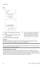
Страница 21: ...nsmit data Output 2 Tr data Transmit data Output 3 Re Data Receive data Input 4 n c n c 5 n c n c 6 Re Data Receive data Input 7 n c n c 8 n c n c Tab 9 Pin allocation of the Ethernet interface 5 1 3 6 USB port NOTICE Ingress of moisture through open connections Ingress of moisture can damage the product Fully close all protective flaps of the connections after use to maintain the IP protection cl...

Страница 22: ... to electric shock Use PELV or SELV power circuits exclusively in accordance with EN 61010 2 201 for the electrical power supply of the device Only voltages and circuits that guarantee reliable isolation from dangerous voltages e g by suffi cient insulation and dielectric strength are to be connected to connections terminals or inter faces up to 50 V nominal voltage WARNING Fire hazard due to comp...

Страница 23: ...terminal Incorrect assembly of the cables can impair the mode of operation of the handheld terminal and dam age the handheld terminal Check that the seal is clean and undamaged Check that the cables are not pinched at any point Check that all screws are tight Otherwise the degree of protection cannot be guaranteed This chapter describes how the connecting cable is mounted on the handheld terminal ...

Страница 24: ...9 Position of the TORX screws 1 Loosen the TORX screws on the cover plate with a size 10 TORX screwdriver 2 Open cover Do not damage the cables of the 3 position enabling switch Mounting and installation 24 Festo CDSA D3 RV 2020 08 ...

Страница 25: ...nut is integrated in this passage for mounting the connecting cable 5 Fix the grommet with a size 19 spanner torque 3 Nm 6 Insert the main plug and the RJ45 plug into the sockets provided for this purpose 7 Tighten the strain relief with the spanner Part of the cable sheath should be located inside the housing Make sure that the rubber ring for the strain relief is correctly under the grommet 8 At...

Страница 26: ... Do not pinch the cable Screw on the cover of the connection shaft with all screws and tighten to a torque of 0 8 to 1 0 Nm NOTICE Incorrect handling of the plug when working in the connection shaft Incorrect handling can damage the plugs and the socket Do not use sharp objects to remove the plugs Disconnect the main plug by pulling its wires with fingers Press the locking lever to disconnect the ...

Страница 27: ... controller with remote target visu alisation via an Ethernet interface to enable commissioning and series operation The connection is usually made via an interface housing an interface box or a connection box in which the signals Eth ernet voltage safety engineering are divided As soon as power is supplied to the handheld terminal CDSA D3 RV the run up starts 8 Configuration In the device configu...

Страница 28: ... is opened Fig 12 Device configuration menu System Config 8 1 Diagnosis data With Diagnosis Data diagnostic information of the controller can be collected by triggering a status report This requires a USB stick to be connected to the operator unit The USB stick must fulfil the following criteria Formatted as FAT32 file system Have at least 2 GB of free memory Trigger status report 1 Select Diagnos...

Страница 29: ...ve USB sticks from the handheld terminal 5 Send TGZ file to Festo 8 2 Display Press the Display button to open the display window Display settings can be made in this window To return to the main menu press the Back button Fig 15 Display menu Brightness Window for setting the brightness Configuration 29 Festo CDSA D3 RV 2020 08 ...

Страница 30: ...ime until the screen saver is switched on Fig 17 Screen saver In the field Timeout the time can be entered in seconds using the numeric keypad Press the OK button to save the settings and return to the previous window If the Cancel button is pressed the window is closed and the changed settings are not saved Touch calibration Use a touch pen for calibration Press the Touch Calibration button to st...

Страница 31: ...bol four times After successful calibration the calibration window is closed and the Display mask appears Calibra tion of the touchscreen is complete 8 3 Licences Press the Licences button to display the licence information Press the OK button to exit the window 8 4 Network Press the Network button to open the network window The network settings for available Ethernet interfaces and the host IP ad...

Страница 32: ...aining input lines are deactivated Tab 12 Network settings Press the OK button to save the settings and return to the previous window If the Cancel button is pressed the window is closed and the changed settings are not saved 8 5 Version info Press the Version info button to display the software currently installed on the device Operating system version Bootloader version Firmware version Press th...

Страница 33: ...firm the Save Persistently checkbox to save the connection to the controller permanently When the device is restarted the connection to this controller is automatically established A dia logue is displayed for 2 seconds to disconnect the saved connection 6 To set up the connection to the controller press the OK button 7 Start visualisation of the controller 10 Maintenance 10 1 Trigger restart A re...

Страница 34: ...e is created for every backup 10 3 Restore backup install software or firmware update NOTICE Interruption of the restore update process An interruption of the restore update process may destroy the firmware on the components The product can then no longer be operated Leave the USB stick plugged in until the restore update process is completed Maintain the power supply of the module until the resto...

Страница 35: ...USB stick into the handheld terminal CDSA D3 RV 2 Restart disconnect and reconnect power supply 3 Select menu option Backup Restore 4 Select menu option Restore 5 Select service USB stick as the source for the restore or update and confirm with the Restore button Fig 22 Restore menu 6 Confirm dialogue with the OK button Ä The restore or update process is started and a progress bar is displayed The...

Страница 36: ...nloaded 7Z file into the root directory of the USB stick Ä The Update directory and the update img file are created in the root directory 3 Remove the USB stick from the PC 4 Plug USB stick into the handheld terminal CDSA D3 RV while it is disconnected from the power supply 5 Switch on the handheld terminal default Ä The software update is started automatically and the status is output on the disp...

Страница 37: ...ot permitted this may invalidate the conformity of the product If necessary replace the complete product If a safety device is defective the product must be replaced In this case send the defective product unchanged with a description of the fault and application to Festo for analysis Check with your regional Festo contact person to clarify the conditions for the return shipment 12 Disposal ENVIRO...

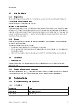
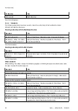
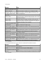
Страница 38: ...en drafting the safety concept the following legally non binding European standards were addi tionally consulted for partial aspects Standard Title General Procedures and safety principles EN ISO 12100 2010 Safety of machinery General principles for design Risk assess ment and risk reduction Design of the 3 position enabling switch EN 60204 1 2006 A1 2009 AC 2010 Safety of machinery Electrical equ...

Страница 39: ... 61131 2 2007 Chapter 11 Programmable logic controllers Part 2 Requirements and tests EN 50178 1997 Equipping of power installations with electronic equipment Requirements for environmental and ambient conditions EN 61131 2 2007 Chapter 4 Programmable logic controllers Part 2 Requirements and tests EN 50178 1997 Equipping of power installations with electronic equipment Requirements for environmen...

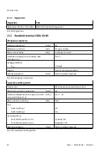
Страница 40: ...al wiring Electrical isolation V AC 500 to all other networks Tab 19 Emergency stop device 3 position enabling switch Output type Electromechanical switching contact Switchable nominal voltage Ue V DC 24 Nominal voltage tolerance range in accord ance with EN 61131 2 V DC 19 2 30 Max nominal current Ie mA 500 B10D Switch setting 2 106 Switch setting 3 106 Actuating forces From switch position 1 to ...

Страница 41: ...eyboard with tactile feed back 20 keys 4 status LEDs Protection class in accordance with EN 61131 2 and or EN 50178 III Degree of protection IP65 CE certification See declaration of conformity è www festo com Tab 21 Technical data general Ambient conditions Operating temperature C 0 40 Storage temperature C 25 70 Relative humidity non condensing 5 95 Vibration resistance in accordance with IEC 600...

Страница 42: ...acteristics Design Housing made of ABS Flammability UL94 V0 Fall proof suitability m 1 5 on industrial floor then at least degree of protection IP54 Tab 25 Mechanical characteristics Dimensions weight Height mm 251 Width mm 212 Depth incl handle and emergency stop device mm 73 Weight g Approx 950 Tab 26 Dimensions weight 13 2 1 Accessories The product may only be operated with the accessories name...

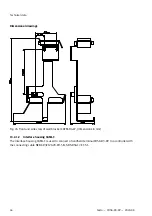
Страница 43: ...FM D4 W The powder coated black wall bracket is used for stationary operation or for storing the handheld ter minal CDSA D3 RV 1 Equipment carrier 2 Cable suspension Fig 23 CAFM D4 W Technical data 43 Festo CDSA D3 RV 2020 08 ...

Страница 44: ...t CAFM D4 W dimensions in mm 13 2 1 2 Interface housing CAMI C The interface housing CAMI C is used to connect a handheld terminal CDSA D3 RV to a controller with the connecting cable NEBC R3Z12G20 KH 5 N SBS RSG17 ET S1 Technical data 44 Festo CDSA D3 RV 2020 08 ...

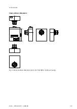
Страница 45: ...Views and basic dimensions Fig 25 Views and basic dimensions in mm of the CAMI C interface housing Technical data 45 Festo CDSA D3 RV 2020 08 ...

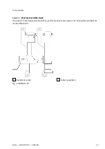
Страница 46: ... the data cables to the interface housing è Fig 4 A crossover cable is required between the handheld terminal CDSA D3 RV and the controller for point to point operation via the Ethernet interface Screening within the control cabinet In many cases there are a number of sources of interference in the control cabinet such as servo drive modules transformers contactors and relays For this reason the c...

Страница 47: ...ion Nominal voltage CDSA D3 RV V DC 24 Nominal voltage tolerance range CDSA D3 RV in accordance with EN 61131 2 V DC 19 2 30 Max interruption duration of the supply voltage CDSA D3 RV corresponding to EN 61131 ms 10 Power consumption Without CDSA D3 RV None With CDSA D3 RV è Tab 21 Technical data general Starting current CDSA D3 RV è Technical data of the handheld terminal Technical data 47 Festo ...

Страница 48: ...teristics Design Housing made of galvanised sheet steel Tab 29 Mechanical characteristics Dimensions weight Width mm 67 2 Height mm 76 1 Depth mm 76 1 Tab 30 Dimensions weight 13 2 1 3 Connecting cable NEBC R3Z12G20 KH xx N SBS RSG17 ET S1 The handheld terminal CDSA D3 RV is available as standard with the following connecting cables NEBC R3Z12G20 KH 5 N SBS RSG17 ET S1 5 m NEBC R3Z12G20 KH 10 N SB...

Страница 49: ... 2 4 4 Emergency stop cir cuit 1 5 5 Emergency stop cir cuit 1 6 6 Enable control circuit 1 pos 7 7 Enable control circuit 1 neg 8 8 Enable control circuit 2 pos 9 12 Enable control circuit 2 neg 10 17 not used 11 9 not used 12 10 not used 11 TD Ethernet 1 13 TD Ethernet 2 14 RD Ethernet 3 15 RD Ethernet 6 16 Tab 31 Pin allocation Technical data 49 Festo CDSA D3 RV 2020 08 ...

Страница 50: ... are harmonised by dir ectives of the European Union These guidelines are suitable for a number of product classes such as machines medical devices or even toys However similar directives have also been developed for other common safety aspects of products such as protection against electricity explosion protection and electromagnetic compatibil ity The directives are directed at the member states...

Страница 51: ...ith safety integration principles Creation and storage of technical documentation State of the art solutions Presumption of conformity by harmonised standards Application of the CE conformity marking The same requirements apply to safety components For safety components it must be demonstrated that a failure or malfunction is not possible or that a malfunction does not lead to a dangerous situ ati...

Страница 52: ... Overall plan of the machine or safety component including control circuit diagrams Hazard and risk analysis Calculations Test results List of the basic safety requirements of the MD applicable to the machine and description of the solutions Applied standards Operating instructions The technical documentation must be retained for at least 10 years after delivery of the last product and must be sub...

Страница 53: ...954 1 A new addition is the Performance Level PL which describes the probability of failure and the ability to detect faults of the safety function The PL is selected by the manufacturer of the machine depending on the actual hazard potential which is determined using the hazard and risk analysis In the case of dangers that can result in irre versible injuries or death a minimum of PL d is usually...

Страница 54: ...reases the risk of misuse because the handheld terminal can be used to start machine movements consciously or unconsciously even at more remote locations where the operating area can no longer be perceived By selecting the appropriate cable length for the handheld terminal the machine operator must therefore find the right compromise between the necessary flex ibility and a reasonable working rang...

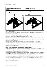
Страница 55: ... emergency stop switches must be installed at selec ted locations around the machine 14 9 Control elements for stopping in an emergency The Machinery Directive does not make any detailed requirements regarding the colours of the control elements for stopping in an emergency The requirement is The command device must have clearly identifiable easily visible and quickly accessible actuators Emergenc...

Страница 56: ...ation in the unplugged state the risk of accidents due to an emergency stop switch that is not ready for operation is considered very low and use of the red yellow identification is permissible The red yellow emergency stop switch must always be connected to the emergency stop circuit of the machine and must switch off the power to the machine or all machines connected to one system stop categorie...

Страница 57: ...keys on the touchscreen An optionally available joystick can also be used to trigger the motion signal Only stop categories 0 or 1 are permitted for the enabling function in accordance with EN 60204 which means that the drives must be shut down in every case with a stop by the 3 position enabling switch In order to prevent improper permanent actuation of the 3 position enabling switch by mechanica...

Страница 58: ... event of insufficient protection the destruction of electrical equipment Atmospheric discharges are simulated in accordance with the international test standard IEC 61000 4 5 for Europe EN 61000 4 5 Testing the interference immunity to impulse voltages The applicable international product standard IEC 61131 2 for Europe EN 61131 2 classifies the areas of application into zones Depending on the ap...

Страница 59: ...unity to fast transient disturbances burst IEC 61000 4 6 Test of interference immunity to conducted disturbances induced by high fre quency fields IEC 61000 4 8 Test of interference immunity to magnetic fields with energy related frequencies IEC 61000 4 11 Test of the interference immunity to voltage dips brief interruptions and voltage fluctuations All of the international standards listed here a...

Страница 60: ... lines communication signals are screened and are routed separately from the control lines supply 3 position enabling switch emergency stop device key switch etc in the CDSA D3 RV cable Supply cables are normally routed unshielded in the control cabinet They are therefore outside the CDSA D3 RV cable shield to avoid coupling with the sensitive data lines The unshielded control and supply cables ar...

Страница 61: ...tion to RJ45 plug The use of pigtails cable tails for contacting the shield via male contacts is not suitable The inductance of such pigtails represents a high impedance resistor for high frequency interference which means an apparent interruption of the cable shield Malfunctions are no longer dissipated and thus have a direct effect on the internal cables Appendix Electromagnetic compatibility 61...

Страница 62: ...binet by shield clamps The shorter the distance between the contacts of the plug housing on the control cabinet and the cable clamp in the control cabinet the better the screening attenuation Fig 33 Shielding within the control cabinet The interference immunity of the device with the connection type shown above is also significantly influenced by the sufficient separation of the control signals fr...

Страница 63: ...ver K Keyboard MB Mounting bracket TS Touchscreen H Hand strap ES Emergency stop EB Enabling button USB USB protective cover CC Connecting cable Tab 34 Abbreviations of materials The resistance of the materials is subdivided into the following classifications in the following table Classification Description Good resistance o Conditional resistance Poor resistance Tab 35 Classification of resistan...

Страница 64: ...ion 10 Ethanol CAS no 000064 17 5 Concentration 95 Hydraulic oil petroleum based CAS no Concentration o Potash CAS no 001310 58 3 Concentration 10 o Linseed oil CAS no 008001 26 1 Concentration o o o Cutting grinding oil CAS no Concentration o o o Methanol CAS no 000067 56 1 Concentration Appendix Resistance to chemicals 64 Festo CDSA D3 RV 2020 08 ...

Страница 65: ... Concentration o o o o o Motor oil CAS no Concentration o o Sodium hydrox ide CAS no 001310 73 2 Concentration 10 o o o Petroleum ether white spirit CAS no 008032 32 4 Concentration Hydrochloric acid CAS no 007647 01 0 Concentration 10 o Lubricating grease CAS no Concentration o Appendix Resistance to chemicals 65 Festo CDSA D3 RV 2020 08 ...

Страница 66: ...Concentration 10 o o Silicone oil CAS no Concentration Spirit CAS no Concentration o Turpentine CAS no Concentration Tab 36 Basic chemical resistance of the materials used in the handheld terminal CDSA D3 RV Appendix Resistance to chemicals 66 Festo CDSA D3 RV 2020 08 ...

Страница 67: ......
Страница 68: ... 2020 all rights reserved to Festo SE Co KG Festo SE Co KG 73734 Esslingen Ruiter Straße 82 Germany 49 711 347 0 www festo com Internet Phone ...

Отзывы: