PEGASUS D
32
EN
cod. 3540U171 - 06/2012 (Rev. 00)
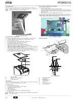
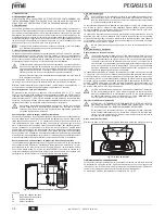
Opening the front panel
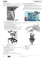
To open the front panel, see the sequence in fig. 18.
B
Before carrying out any operation inside the boiler, disconnect the electrical
power supply and close the gas cock upstream.
fig. 18 - Front panel opening
Cleaning the boiler and flue
To clean the boiler properly (fig. 19):
•
Close the gas cock ahead of the boiler and disconnect the electrical power.
•
Remove the front panel of the boiler.
•
Lift the casing cover by pressing upwards.
•
Remove the insulation placed over the anti-backflow device.
•
Remove the fume chamber closing plate.
•
Remove the burner assembly (see next section).
•
Clean from the top downwards, using a flue brush.
•
Clean the fume evacuation ducts between the cast iron elements of the boiler shell
with a vacuum cleaner.
•
Carefully refit all the previously removed parts and check the tightness of the gas
circuit and the combustion ducts.
•
During cleaning operations be careful not to damage the fume thermostat bulb at
the back of the fume chamber.
fig. 19 - Boiler cleaning
1
Casing cover
2
Fume chamber closing plate
3
Flue brush
7
Combustion analysis plug
Combustion analysis
A point for sampling fumes has been included inside the boiler, in the upper part of the
anti-backflow device (detail 7 - fig. 19).
To take the sample:
1.
Remove the upper panel of the boiler
2.
Remove the insulation placed over the anti-backflow device;
3.
Open the fume sampling point;
4.
Insert the probe;
5.
Activate the TEST mode
6.
Wait 10-15 minutes for the boiler to stabilise*
7.
Take the measurement.
A
Analyses made with an unstabilised boiler can cause measurement errors.
Removing and cleaning the burner assembly
To remove the burner assembly:
•
Disconnect the electrical power supply and turn off the gas ahead of the boiler;
•
Undo the nut fixing the gas supply pipe ahead of the gas valve;
•
Undo the two nuts fixing the combustion chamber door to the cast iron elements of
the boiler (fig. 20)
•
Remove the burner assembly and combustion chamber door.
Then check and clean the main burners and pilot burner. Use a non-metal brush or com-
pressed air to clean the burners; never use chemical products.
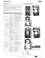
fig. 20 - Removing the burners
Pilot burner assembly
fig. 21 - Pilot burner
1
Combustion chamber door
2
Inspection door
3
Pilot burner
4
Ignition electrode
5
Detection electrode
6
Pilot nozzle
7
High voltage cable
8
Gas supply pipe
3
2
1
7
3
3 ÷ 4 mm
5
4
8
Содержание PEGASUS D
Страница 62: ......
Страница 63: ......
Страница 64: ...FERROLI S p A Via Ritonda 78 a 37047 San Bonifacio Verona ITALY www ferroli it...


