background image

PEGASUS D

30

EN

cod. 3540U171  -  06/2012  (Rev. 00)

3. 2. INSTALLATION8
3.1 General Instructions

BOILER INSTALLATION MUST ONLY BE PERFORMED BY QUALIFIED PERSON-
NEL, IN ACCORDANCE WITH ALL THE INSTRUCTIONS GIVEN IN THIS TECHNICAL
MANUAL, THE PROVISIONS OF CURRENT LAW, THE PRESCRIPTIONS OF NA-
TIONAL AND LOCAL STANDARDS AND THE RULES OF PROPER WORKMANSHIP.

3.2 Place of installation

The boiler unit must be installed in a specific room with ventilation openings to the out-
side as prescribed by current regulations. If there are several burners or suction units
that can work together in the same room, the ventilation openings must be sized for si-
multaneous operation of all the units. The place of installation must be free of flammable
materials or objects, corrosive gases, powders or volatile substances that, conveyed by
the burner fan, can obstruct the internal lines of the burner or the combustion head. The
room must be dry and not exposed to rain, snow or frost.

A

If the unit is enclosed in a cabinet or mounted alongside, a space must be pro-
vided for removing the casing and for normal maintenance operations.

3.3 Plumbing connections

The heating capacity of the unit must be previously established by calculating the build-
ing's heat requirement according to the current regulations. The system must be provid-
ed with all the components for correct and regular operation. It is advisable to install
shutoff valves between the boiler and heating system allowing the boiler to be isolated
from the system if necessary.

B

The safety valve outlet must be connected to a funnel or collection pipe to pre-
vent water spurting onto the floor in case of overpressure in the heating circuit.
Otherwise, if the discharge valve cuts in and floods the room, the boiler manu-
facturer cannot be held liable.
Do not use the water system pipes to earth electrical appliances.

Before installation, carefully wash all the pipes of the system to remove any residuals or
impurities that could affect proper operation of the unit.
Carry out the relevant connections according to the diagram in cap. 5.1 and the symbols
given on the unit.

Water system characteristics

In the presence of water harder than 25° Fr (1°F = 10ppm CaCO3), use suitably treated
water in order to avoid possible scaling in the boiler. Treatment must not reduce the hard-
ness to values below 15°F (Decree 236/88 for uses of water intended for human con-
sumption). Treatment of the water used is indispensable in case of very large systems
or with frequent introduction of replenishing water in the system.

B

If water softeners are installed at the boiler cold water inlet, make sure not to
reduce the water hardness too much, as this could cause early deterioration of
the magnesium anode in the hot water tank.

Antifreeze system, antifreeze fluids, additives and inhibitors

The boiler is equipped with an antifreeze system that turns on the boiler in heating mode
when the system delivery water temperature falls under 6°C. The device will not come
on if the electricity and/or gas supply to the unit are cut off. If it becomes necessary, it is
permissible to use antifreeze fluid, additives and inhibitors only if the manufacturer of
these fluids or additives guarantees they are suitable for this use and cause no damage
to the heat exchanger or other components and/or materials of the boiler unit and sys-
tem. It is prohibited to use generic antifreeze fluid, additives or inhibitors that are not ex-
pressly suited for use in heating systems and compatible with the materials of the boiler
unit and system.

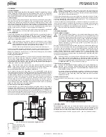
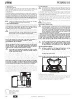
Connection to a storage tank for domestic hot water production

The unit's electronic board is arranged for managing an external storage tank for domes-
tic hot water production. Carry out the plumbing connections according to the diagram
fig. 14 (pumps and non-return valves must be supplied separately). Carry out: electrical
connections as shown in the wiring diagram incap. 5.4. A probe FERROLImust be used.
At the next lighting, the boiler's control system recognises the presence of the hot water
tank probe and automatically configures the DHW function, activating the display and rel-
evant controls.

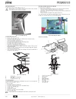
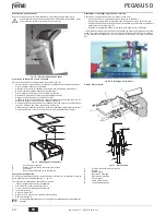
fig. 14 - Diagram of connection to external hot water tank

Key

8

Domestic hot water outlet

9

Cold water inlet

10

System delivery

11

System return

3.4 Gas connection

B

Before making the connection, make sure the unit is arranged for operation with
the type of fuel available and carefully clean all the system gas pipes to remove
any residuals or impurities that could affect proper operation of the boiler.

The gas must be connected to the respective union (see fig. 25) in conformity with cur-
rent regulations, with a rigid metal pipe or with a continuous surface flexible s/steel tube,
installing a gas cock between the system and boiler. Make sure all the gas connections
are tight.
The capacity of the gas meter must be sufficient for the simultaneous use of all the ap-
pliances connected to it. The diameter of the gas pipe leaving the boiler does not deter-
mine the diameter of the pipe between the unit and the meter; it must be chosen
according to its length and pressure losses, in conformity with the current regulations.

B

Do not use the gas pipes to earth electrical appliances.

3.5 Electrical connections
Connection to the electrical grid

B

The unit's electrical safety is only guaranteed when correctly connected to an
efficient earthing system executed according to current safety standards. Have
the efficiency and suitability of the earthing system checked by professionally
qualified personnel. The manufacturer is not responsible for any damage
caused by failure to earth the system. Also make sure that the electrical system
is adequate for the maximum power absorbed by the unit, as specified on the
boiler dataplate.

The boiler is prewired and provided with a Y-cable and plug for connection to the elec-
tricity line. The connections to the grid must be made with a permanent connection and
equipped with a bipolar switch whose contacts have a minimum opening of at least 3
mm, interposing fuses of max. 3A between the boiler and the line. It is important to re-
spect the polarities (LINE: brown wire / NEUTRAL: blue wire / EARTH:  yellow-green
wire) in making connections to the electrical line. During installation or when changing
the power cable, the earth wire must be left 2 cm longer than the others.

B

The user must never change the unit's power cable. If the cable gets damaged,
switch off the unit and have it changed solely by professionally qualified person-
nel. If changing the electric power cable, use solely 

“HAR H05 VV-F”

 3x0.75

mm2 cable with a maximum outside diameter of 8 mm.

Room thermostat (optional)

B

IMPORTANT: THE ROOM THERMOSTAT MUST HAVE VOLTAGE-FREE
CONTACTS. CONNECTING 230 V TO THE ROOM THERMOSTAT TERMI-
NALS WILL PERMANENTLY DAMAGE THE ELECTRONIC BOARD.
When connecting time controls or a timer, do not take the power supply for
these devices from their breaking contacts Their power supply must be by
means of direct connection from the mains or with batteries, depending on the
kind of device.

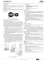
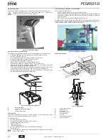
Accessing the electrical terminal block

Undo the two screws 

“A”

 located on the top part of the control panel and remove the

cover.

fig. 15 - Accessing the terminal board

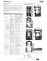
3.6 Connection to the flue

The flue connection pipe diameter must not be less than that of the connection on the
anti-backflow device. Starting from the anti-backflow device it must have a vertical sec-
tion at least 50 cm long. Comply with the current standards regarding installation and siz-
es of the flues and connection pipe.
The diameter of the anti-backflow device collar is given in fig. 22 - fig. 23.

8

9

10

11

A

Содержание PEGASUS D

Страница 1: ...E E LA MANUTENZIONE ES INSTRUCCIONES DE USO INSTALACI N Y MANTENIMIENTO TR KULLANMA KURULUM VE BAK M TALIMATLAR EN INSTRUCTIONS FOR USE INSTALLATION AND MAINTENANCE FR INSTRUCTIONS D UTILISATION D INS...

Страница 2: ...a digitale con funzionalit avanzate di termoregolazione A La caldaia predisposta per il collegamento ad un bollitore esterno per acqua calda sanitaria opzionale In questo manuale tutte le funzioni re...

Страница 3: ...e modificarla con i tasti sanitario part 1 e 2 fig 1 Regolare la curva desiderata da 1 a 10 secondo la caratteristica fig 11 Regolando la curva a 0 la regolazione a temperatura scorrevole risulta disa...

Страница 4: ...e di acqua calda sanitaria Effettuare gli allacciamenti idraulici secon do lo schema fig 14 pompe e valvole di non ritorno devono essere fornite a parte Effettuare collegamenti elettrici come indicato...

Страница 5: ...golazione della pressione 4 2 Messa in servizio B La messa in servizio deve essere effettuata da Personale Qualificato e di sicura qualificazione Verifiche da eseguire alla prima accensione e dopo tut...

Страница 6: ...chiusura della camera fumi 3 Scovolo 7 Tappo per l analisi della combustione Analisi della combustione All interno della caldaia nella parte superiore dell antirefouleur stato inserito un punto di pr...

Страница 7: ...po l inter vento del termostato fumi il funzionamento della caldaia viene impe dito per 20 minuti Contatto termostato fumi aperto Verificare il termostato Cablaggio interrotto Verificare il cablaggio...

Страница 8: ...80 4x2 80 Pressione gas alimentazione G20 mbar 20 20 20 Pressione max valle valvola gas G20 mbar 15 13 15 Pressione min valle valvola gas G20 mbar 2 5 2 5 2 5 Portata gas max G20 m3 h 2 68 3 69 5 24 P...

Страница 9: ...82 Elettrodo rilevazione 126 Termostato fumi 130 Circolatore sanitario opzionale 138 Sonda esterna non fornito 139 Unit ambiente non fornito 246 Trasduttore di pressione 278 Sensore doppio Sicurezza...

Страница 10: ...n effettuato a cura dell azienda inosservanza delle istruzioni e delle avvertenze previste dall azienda produttrice e riportate sui manuali di utilizzo a corredo del prodotto errata installazione o in...

Страница 11: ...gua sanitaria descritas en este manual son v lidas s lo si el acumulador sa nitario opcional est conectado como se indica en sec 3 3 2 2 Panel de mandos fig 1 Panel de control Leyenda 1 Tecla 2 Tecla...

Страница 12: ...1 Si se elige la curva 0 la regulaci n con temperatura adaptable queda desactivada fig 9 Curva de compensaci n Si se pulsan las teclas de la calefacci n 3 y 4 fig 1 se accede al desplazamiento paralel...

Страница 13: ...ca de la caldera puede controlar un acumulador exterior para la pro ducci n de agua caliente sanitaria Realizar las conexiones hidr ulicas seg n el esque ma fig 14 las bombas y las v lvulas antirretor...

Страница 14: ...ene que ser efectuada por personal cualificado Con troles que se han de efectuar durante el primer encendido tras las operacio nes de mantenimiento que exigen desconectar la caldera y despu s de toda...

Страница 15: ...e de la c mara de humos 3 Cepillo 7 Tap n para el an lisis de la combusti n An lisis de la combusti n Dentro de la caldera en la parte superior del cortatiro hay un punto de toma de humo 7 fig 19 Para...

Страница 16: ...s la cual la caldera queda bloqueada durante 20 segundos Contacto del termostato de humos abierto Controlar el termostato Cableado interrumpido Controlar el cableado Chimenea mal dimensio nada u obstr...

Страница 17: ...taci n gas G20 mbar 20 20 20 Presi n m xima despu s de la v lvula de gas G20 mbar 15 13 15 Presi n m nima despu s de la v lvula de gas G20 mbar 2 5 2 5 2 5 Caudal m ximo de gas G20 m3 h 2 68 3 69 5 24...

Страница 18: ...do 82 Electrodo de detecci n 126 Termostato de humos 130 Bomba de circulaci n del agua sanitaria opcional 138 Sonda exterior no suministrada 139 Unidad ambiente no suministrada 246 Transductor de pres...

Страница 19: ...go de los componentes siendo por cuenta del usuario la mano de obra y el desplazamiento Cuerpo de las calderas de chapa Un a o Cuerpo de las calderas de hierro fundido Un a o cada elemento Cuerpo de c...

Страница 20: ...ayarlama fonksiyonlar na sahip dijital aray zl bir mikroi lemcidir A Kombi s cak musluk suyu retimi i in harici bir s t c kazana ba lanmak zere tasarlanm t r opsiyonel Bu kullan m k lavuzundaki s cak...

Страница 21: ...ak k s m 1 ve 2 ek 1 de i tirilmesi m mk nd r E riyi 1 ile 10 saniye aras nda istedi iniz gibi ayarlay n z ek 11 E ri 0 a ayarland nda s cakl k ak ayarlamas devre d kal r ek 9 Kompenzasyon e risi Is t...

Страница 22: ...ap n z pompalar ve geri d n valflar ayr ca tedarik edilmelidir A a dakiler ger ekle tiriniz cap 5 4 k sm ndaki elektrik emas nda g sterilen elektrik ba lant lar Bir FERROLI sen s r n n kullan lmas ger...

Страница 23: ...Kalifiye Personel ve yeterlili e sahip ki iler ta raf ndan yap lmal d r lk al t rma an nda ve sistemden ba lant n n kesilmesi veya emniyet cihazlar nda ya da kombinin di er aksamlar nda bir bak m i le...

Страница 24: ...1 Muhafaza kapa 2 Duman odas kapatma plakas 3 F r a 7 Yanma analizi t pas Yanma analizi Dumanlar n rneklemesi amac yla bir nokta kombinin i erisinde geri ak nleme cihaz n n st k sm nda bulunmaktad r k...

Страница 25: ...ostat n n konta a kt r Termostat kontrol ediniz Kablolarda kopukluk var Kablo tesisat n kontrol ediniz Bacan n ebatlar yanl t r veya t kal durumdad r Duman kanal n de i tiriniz A06 Ate leme a amas nda...

Страница 26: ...lar G20 n x 2x2 80 3x2 80 4x2 80 Besleme gaz bas nc G20 mbar 20 20 20 Gaz G20 valf y n nde maks bas n mbar 15 13 15 Gaz G20 valf y n nde min bas n mbar 2 5 2 5 2 5 Maks gaz k G20 m3 s 2 68 3 69 5 24...

Страница 27: ...elektrotu 126 Duman termostat 130 Musluk suyu devir daim pompas opsiyonel 138 Harici sens r cihazla birlikte verilmez 139 Oda nitesi cihazla birlikte verilmez 246 Bas n d r c 278 ift sens r Emniyet Is...

Страница 28: ...ranged for connection to an external storage tank for hot water production optional In this manual all the functions relevant to domestic hot water production are only active with the optional hot wat...

Страница 29: ...d 2 fig 1 Adjust the required curve from 1 to 10 according to the characteristic fig 11 By setting the curve to 0 sliding temperature adjustment is disabled fig 9 Compensation curve Press the heating...

Страница 30: ...Carry out the plumbing connections according to the diagram fig 14 pumps and non return valves must be supplied separately Carry out electrical connections as shown in the wiring diagram incap 5 4 A...

Страница 31: ...5 Protection cap 6 Pressure adjustment screw 4 2 Start up B System start up must be carried out by Qualified Personnel Checks to be made at first lighting and after all maintenance operations that in...

Страница 32: ...e brush 7 Combustion analysis plug Combustion analysis A point for sampling fumes has been included inside the boiler in the upper part of the anti backflow device detail 7 fig 19 To take the sample 1...

Страница 33: ...Vent the system F04 Fume thermostat acti vated after activation of the fume thermostat boiler operation is pre vented for 20 minutes Fume thermostat contact open Check the thermostat Wiring disconnect...

Страница 34: ...2x2 80 3x2 80 4x2 80 Gas supply pressure G20 mbar 20 20 20 Max pressure downstream of gas valve G20 mbar 15 13 15 Min pressure downstream of gas valve G20 mbar 2 5 2 5 2 5 Max gas delivery G20 m3 h 2...

Страница 35: ...Detection electrode 126 Fume thermostat 130 DHW circulating pump optional 138 External probe not supplied 139 Room unit not supplied 246 Pressure transducer 278 Double sensor Safety Heating DSP05 7 6...

Страница 36: ...temp rature A Un ballon ext rieur option servant la production d eau chaude sanita ire peut tre raccord la chaudi re Dans ce manuel toutes les fonc tions relatives la production d eau chaude sanitaire...

Страница 37: ...t ristique fig 11 Si la courbe est r gl e sur 0 le r glage de la temp rature volutive est d sactiv fig 9 Courbe de compensation Appuyer sur les touches chauffage rep 3 et 4 fig 1 pour passer au d plac...

Страница 38: ...eau chaude sanitaire La carte lectronique de l appareil est pr vue pour la gestion d un ballon externe pour la production d eau chaude sanitaire Effectuer les raccordements hydrauliques selon le sch m...

Страница 39: ...ce B La mise en service doit tre effectu e par du personnel qualifi disposant du savoir faire et de l expertise n cessaires V rifications effectuer au premier allumage et apr s toutes les op rations d...

Страница 40: ...Bouchon pour l analyse de la combustion Analyse de la combustion Un point de pr l vement des fum es a t pr vu l int rieur de la chaudi re dans la partie sup rieure de l antirefouleur rep 7 fig 19 Pour...

Страница 41: ...ement du ther mostat s curit fum es apr s son d clenche ment le fonctionnement de la chaudi re est d sactiv pendant 20 minutes Contact de thermostat s curit fum es ouvert V rifier le thermostat C blag...

Страница 42: ...ur G20 nbre x 2x2 80 3x2 80 4x2 80 Pression d alimentation gaz G20 mbar 20 20 20 Pression maxi en aval vanne gaz G20 mbar 15 13 15 Pression mini en aval vanne gaz G20 mbar 2 5 2 5 2 5 D bit gaz maxi G...

Страница 43: ...lectrode de d tection 126 Thermostat fum es 130 Circulateur eau chaude sanitaire option 138 Sonde ext rieure non fournie 139 Unit d ambiance non fournie 246 Transducteur de pression 278 Capteur double...

Страница 44: ...19 20 21 22 23 24 25 26 27 2 3 2 B e sez 3 3 3 120 FH 5 FH on off 9 1 1 4 on off 9 1 1 5 9 1 B sez 3 3 eco comfort m o d e r e s e t bar 5 7 9 10 2 1 8 6 4 3 16 17 18 20 21 22 23 25 24 26 27 19 eco co...

Страница 45: ...1 0 F37 13 13 A 120 FH eco comfort m o d e r e s e t eco bar eco comfort m o d e r e s e t eco bar eco comfort m o d e r e s e t eco bar ECO COMFORT Eco nomy 7 1 Comfort 7 1 20 30 40 50 60 70 80 90 8...

Страница 46: ...U cod 3540U171 06 2012 Rev 00 3 3 1 3 2 A 3 3 B cap 5 1 25 Fr 1 F 10 CaCO3 15 F 236 88 B 6 C 14 cap 5 4 FERROLI 14 8 9 10 11 3 4 B 25 B 3 5 B Y 3 3A 2 B HAR H05 VV F 3x0 75 2 8 B 230 A 15 3 6 0 5 22 2...

Страница 47: ...16 TEST TEST TEST 15 PEGASUS D 17 cap 5 2 1 5 17 2 2 17 3 6 17 cap 5 2 4 2 3 G20 G25 G30 G31 1 cap 5 3 2 3 17 G20 G25 D 17 G30 G31 E 17 3 4 17 A B C D G20 G25 E G30 G31 1 2 3 4 5 6 4 2 B 1 17 120 FH...

Страница 48: ...PEGASUS D 48 RU cod 3540U171 06 2012 Rev 00 18 B 18 19 19 1 2 3 7 7 19 1 2 3 4 5 TEST 6 10 15 7 A 20 20 21 1 2 3 4 5 6 7 8 3 2 1 7 3 3 4 mm 5 4 8...

Страница 49: ...11 44 126 246 273 275 A01 A02 A03 F04 20 A06 F10 1 F14 2 i F34 170 F35 F37 F39 F40 o A41 F42 F47 A48 A49 400 850 246 44 275 273 44 275 615 70 10 7 111 181 582 261 37 10 11 7 112 109 126 500 850 246 4...

Страница 50: ...2 P Pmax 80 60 C 90 9 91 7 90 9 30 91 3 91 5 91 6 92 42 CE NOx 2 2 2 G20 x 2 x 2 80 3 x 2 80 4 x 2 80 G20 20 20 20 G20 15 13 15 G20 2 5 2 5 2 5 G20 3 2 68 3 69 5 24 G20 3 1 07 1 58 2 08 G31 x 2 x 1 75...

Страница 51: ...1 82 126 130 138 139 246 278 DSP05 7 6 5 4 3 2 1 11 10 9 8 7 6 5 4 3 2 1 T1 T2 X7 7 6 5 4 3 2 1 6 5 4 3 2 1 X5 F1 F2 X1 X2 X4 X3 X6 X8 X10 2 1 T T 278 GND 5V OUT 246 L N 230V 50Hz 138 139 72 L N 4 5 6...

Страница 52: ...9 10 16 17 18 19 20 21 22 23 24 25 26 27 Estate 2 3 2 B i i sez 3 3 i i i i i 3 i 120 FH i 5 i FHI on off 9 1 1 4 i i i i on off i 9 1 1 5 i i ON OFF 9 1 B i i i i i i i i sez 3 3 eco comfort m o d e...

Страница 53: ...10 10 1 i i i i i 11 12 i i A i i i i i i 1 5 1 1 i 1 0 i i i i i F37 13 13 A i i i i 120 FH eco comfort m o d e r e s e t eco bar eco comfort m o d e r e s e t eco bar eco comfort m o d e r e s e t e...

Страница 54: ...i i CaCO3 i i i i i i i 15 F I i i 236 88 B i i i i i i 6 C i i i i i i i i i 14 i cap 5 4 FERROLI i i i i i i i 14 i i 8 9 10 i 11 3 4 B i i i i i i i i i i i i i i i 25 i i i i i i i i i i i i i i...

Страница 55: ...5 17 2 i i 2 17 i 3 i 6 17 i i cap 5 2 4 i i i i i i 2 3 i i i i i G20 G25 G30 G31 1 i cap 5 3 2 i i 3 17 i G20 G25 D 17 G30 G31 E 17 3 i i i 4 17 A B C i D G20 G25 E G30 G31 1 2 i 3 4 5 6 4 2 B i i i...

Страница 56: ...i i i 19 i i i i i i i i i i i i i i i i i i i i i i i i i i 19 1 2 i i 3 7 i i i i i i i 7 19 1 i i 2 i i i i 3 i i i i 4 5 i TEST 6 10 15 7 A i i i i i i i i i i i i i i i i i i i 20 i i i i i i i i...

Страница 57: ...PEGASUS D 45 7 10 11 44 126 246 273 275 A01 A02 A03 F04 20 A06 F10 1 F14 2 F34 170 F35 F37 F39 F40 A41 F42 F47 A48 A49 400 850 246 44 275 273 44 275 615 70 10 7 111 181 582 261 37 10 11 7 112 109 126...

Страница 58: ...2 P i i i Pmax 80 60 C 90 9 91 7 90 9 i i i 30 91 3 91 5 91 6 92 42 EEC NOx 2 2 2 G20 x 2x2 80 3x2 80 4x2 80 G20 20 20 20 G20 15 13 15 G20 2 5 2 5 2 5 G20 3 2 68 3 69 5 24 G20 3 1 07 1 58 2 08 G31 x...

Страница 59: ...1 82 126 130 138 139 246 278 DSP05 7 6 5 4 3 2 1 11 10 9 8 7 6 5 4 3 2 1 T1 T2 X7 7 6 5 4 3 2 1 6 5 4 3 2 1 X5 F1 F2 X1 X2 X4 X3 X6 X8 X10 2 1 T T 278 GND 5V OUT 246 L N 230V 50Hz 138 139 72 L N 4 5 6...

Страница 60: ...ettiva Compatibilit Elettromagnetica 2004 108 Presidente e Legale rappresentante Cav del Lavoro Dante Ferroli IT Uygunluk beyani malat i FERROLI S p A Adres Via Ritonda 78 a 37047 San Bonifacio VR bu...

Страница 61: ...8 Dante Ferroli RU D claration de conformit Le constructeur FERROLI S p A Adresse Via Ritonda 78 a 37047 San Bonifacio VR d clare que cet appareil est conforme aux directives CEE ci dessous Directives...

Страница 62: ......

Страница 63: ......

Страница 64: ...FERROLI S p A Via Ritonda 78 a 37047 San Bonifacio Verona ITALY www ferroli it...

Отзывы: