background image

PEGASUS D

22

TR

cod. 3540U171  -  06/2012  (Rev. 00)

3. KURULUM
3.1 Genel talimatlar

KOMB

ø

, BU TEKN

ø

K KULLANIM K

ø

TAPÇI

ö

INDA BEL

ø

RT

ø

LMEKTE OLAN BÜTÜN TAL

ø

MA-

TLARA, YÜRÜRLÜKTE OLAN 

ø

LG

ø

L

ø

 ULUSAL STANDARTLARA VE YEREL TÜZÜKLERE

UYGUN B

ø

ù

EK

ø

LDE, 

øù

Ç

ø

L

ø

K KURALLARINA TAM OLARAK UYGUNLUK 

ø

Ç

ø

NDE VE SA-

DECE KAL

ø

F

ø

YE B

ø

R PERSONEL TARAFINDAN MONTE ED

ø

LMEL

ø

D

ø

R.

3.2 Kurulum yeri

Kombi, d

Õ

ú

ar

Õ

ya havaland

Õ

rma aç

Õ

kl

Õ

klar

Õ

 olan uygun mekanlara, yürürlükte bulunan standar-

tlara göre monte edilmelidir. Ayn

Õ

 mekânda ve ayn

Õ

 anda çal

Õ

ú

acak birden fazla brülör veya

aspiratör varsa, havaland

Õ

rma aç

Õ

kl

Õ

klar

Õ

 tüm cihazlar

Õ

n birlikte çal

Õ

ú

mas

Õ

na olanak sa

÷

la-

yacak 

ú

ekilde boyutland

Õ

r

Õ

lmal

Õ

d

Õ

r. Cihaz

Õ

n monte edilece

÷

i yerin alev al

Õ

c

Õ

 madde ve nesne-

lerden, a

ú

Õ

nd

Õ

r

Õ

c

Õ

 gazlardan, havaland

Õ

rma cihaz

Õ

 taraf

Õ

ndan çekildi

÷

inde brülörün iç kanal

yollar

Õ

n

Õ

 ve yanma kafas

Õ

n

Õ

 t

Õ

kayabilecek toz veya uçucu maddelerden ar

Õ

t

Õ

lm

Õ

ú

 olmas

Õ

 gerek-

mektedir. Ortam kuru olmal

Õ

 ve ya

÷

mur, kar ya da ayaza maruz kalmamal

Õ

d

Õ

r.

A

E

÷

er cihaz bir mobilya içerisine veya yak

Õ

n

Õ

na monte edilecekse, muhafazan

Õ

n

ç

Õ

kart

Õ

labilmesi için ve normal bak

Õ

m i

ú

leri için bir aç

Õ

kl

Õ

k b

Õ

rak

Õ

lmal

Õ

d

Õ

r.

3.3 Su ba

÷

lant

Õ

lar

Õ

Cihaz

Õ

Õ

s

Õ

tma kapasitesi, mevcut tüzüklere göre binan

Õ

n/evin 

Õ

s

Õ

 gereksinimini daha ön-

ceden hesaplamak suretiyle ayarlanmal

Õ

d

Õ

r. Sistem, do

÷

ru ve düzenli bir çal

Õ

ú

ma için ge-

rekli tüm bile

ú

enlerle donat

Õ

lm

Õ

ú

 olmal

Õ

d

Õ

r. E

÷

er gerekirse, kombinin sistemden

izolasyonunu sa

÷

layabilmek amac

Õ

yla kombi ile 

Õ

s

Õ

tma sistemi aras

Õ

na bir açma-kapama

valf

Õ

n

Õ

n monte edilmesi önerilebilir.

B

Is

Õ

tma devresinde bir a

ú

Õ

r

Õ

-bas

Õ

nç olmas

Õ

 durumunda suyun zemin üzerine

dökülmesini önlemek amac

Õ

yla emniyet valf

Õ

 ç

Õ

k

Õ

ú

Õ

, bir bacaya veya toplama

borusuna ba

÷

lanmal

Õ

d

Õ

r. E

÷

er bunu yapam

Õ

yorsan

Õ

z, tahliye valf

Õ

 hata verir ve

oday

Õ

 su basar, bu durumdan üretici 

ú

irket sorumlu tutulamaz.

Elektrikli cihazlar

Õ

 topraklamak amac

Õ

yla su sistemini asla kullanmay

Õ

n

Õ

z.

Cihaz

Õ

n iyi bir 

ú

ekilde çal

Õ

ú

mas

Õ

n

Õ

 etkileyebilecek olan kal

Õ

nt

Õ

 veya birikintileri ç

Õ

karmak için

montaj i

ú

leminden önce sistemin/tesisat

Õ

n bütün borular

Õ

n

Õ

 dikkatli bir 

ú

ekilde y

Õ

kay

Õ

n

Õ

z.

Ba

÷

lant

Õ

lar

Õ

, ilgili ba

÷

lant

Õ

 noktalar

Õ

na cap. 5.1 k

Õ

sm

Õ

nda belirtildi

÷

i gibi ve cihaz üzerinde

belirtilen sembollere riayet ederek yap

Õ

n

Õ

z.

Sistem suyunun özellikleri

Suyun 25° Fr sertlik derecesinden (1°F = 10ppm CaCO3) daha sert olmas

Õ

 halinde, kom-

bide sert suyun sebep oldu

÷

u kireç olu

ú

umlar

Õ

n

Õ

 önlemek amac

Õ

yla uygun su kullan

Õ

m

Õ

n

Õ

öneririz. Ancak, yap

Õ

lan i

ú

lemin su sertli

÷

ini sertli

÷

i 15°F'nin alt

Õ

nda bir de

÷

ere dü

ú

ürme-

mesi gerekmektedir (DPR 236/88 - 

ø

nsanlar

Õ

n su tüketimine yönelik kullan

Õ

mlar için). Çok

büyük sistemlerde veya sistemde suyun çok s

Õ

k bir 

ú

ekilde yeniden ikmal edildi

÷

i duru-

mlarda suyu i

ú

lemden geçirmek gerekmektedir.

B

E

÷

er kombinin so

÷

uk su giri

ú

 k

Õ

sm

Õ

na kireç gidericiler/çözücüler yerle

ú

tirilirse,

suyun sertlik derecesinin a

ú

Õ

r

Õ

 dü

ú

ürülmemesine özellikle dikkat ediniz, aksi

halde kazan

Õ

n magnezyum anodu vaktinden önce eriyip yok olabilir.

Anti-friz sistemi, anti-friz s

Õ

v

Õ

s

Õ

, eklentiler ve inhibitörler

Kombi, sistem ç

Õ

k

Õ

ú

 suyunun s

Õ

cakl

Õ

k de

÷

eri 6 °C'nin alt

Õ

na dü

ú

÷

ü zaman kombiyi

Õ

s

Õ

tma moduna geçiren bir anti-friz sistemi ile donat

Õ

lm

Õ

ú

t

Õ

r. E

÷

er cihaza gelen elektrik ve/

veya gaz beslemesi kesilir ise cihaz çal

Õ

ú

mayacakt

Õ

r. E

÷

er gerekirse, anti-friz s

Õ

v

Õ

s

Õ

n

Õ

n,

kimyasal ek/katk

Õ

 maddelerinin ve inhibitörlerin kullan

Õ

m

Õ

na (e

÷

er bu s

Õ

v

Õ

lar

Õ

n veya kim-

yasal katk

Õ

 maddelerinin üretici 

ú

irketi, bu ürünlerin bu amaç için kullan

Õ

m

Õ

n

Õ

n uygun ol-

du

÷

unu ve bunlar

Õ

Õ

s

Õ

  e

ú

anjörüne veya di

÷

er bile

ú

enlere ve/veya kombi ünitesi ile

sistemin aksamlar

Õ

na zarar vermeyece

÷

ini garanti ediyorsa) izin verilebilir. Is

Õ

tma si-

stemlerinde kullan

Õ

mlar

Õ

n

Õ

n uygun oldu

÷

u ve kombi ünitesi ile sistemlerinin aksamlar

Õ

 ile

uyumlu oldu

÷

u aç

Õ

kça beyan edilmeyen normal/s

Õ

radan antifriz s

Õ

v

Õ

lar

Õ

n

Õ

n, kimyasal ek

maddelerin veya inhibitörlerin kullan

Õ

lmas

Õ

 yasakt

Õ

r.

Bir musluk suyu 

Õ

s

Õ

tma kazan

Õ

na ba

÷

lant

Õ

Cihaz

Õ

n elektronik kart

Õ

, s

Õ

cak musluk suyu üretimi için tak

Õ

lan harici bir 

Õ

s

Õ

t

Õ

c

Õ

 kazan

Õ

n

Õ

yönetmek üzere tasarlanm

Õ

ú

t

Õ

r. Hidrolik ba

÷

lant

Õ

lar

Õ


ú

emaya (

ú

ek. 14) göre yap

Õ

n

Õ

z

(pompalar ve geri-dönü

ú

 valflar

Õ

 ayr

Õ

ca tedarik edilmelidir). A

ú

a

÷

Õ

dakiler gerçekle

ú

tiriniz:

cap. 5.4 k

Õ

sm

Õ

ndaki elektrik 

ú

emas

Õ

nda gösterilen elektrik ba

÷

lant

Õ

lar

Õ

. Bir FERROLI sen-

sörünün kullan

Õ

lmas

Õ

 gereklidir. Kombi kontrol sistemi, bir sonraki çal

Õ

ú

t

Õ

rmada 

Õ

s

Õ

t

Õ

c

Õ

 ka-

zan sensörünü tan

Õ

yacakt

Õ

r ve gösterge ekran

Õ

 ve s

Õ

cak su fonksiyonu ile ilgili kontrolleri

aktive etmek suretiyle otomatik olarak yap

Õ

land

Õ

racakt

Õ

r.

ú

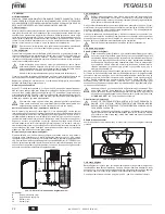
ek. 14 - Harici bir 

Õ

s

Õ

t

Õ

c

Õ

 kazan

Õ

na ba

÷

lant

Õ


ú

emas

Õ

Õ

klamalar

8

S

Õ

cak musluk suyu ç

Õ

k

Õ

ú

Õ

9

So

÷

uk musluk suyu giri

ú

i

10

Sistem ç

Õ

k

Õ

ú

Õ

11

Sistem giri

ú

i

3.4 Gaz ba

÷

lant

Õ

s

Õ

B

Ba

÷

lant

Õ

 i

ú

lemini yapmadan önce, cihaz

Õ

n mevcut yak

Õ

t tipi ile çal

Õ

ú

mak üzere

ayarlanm

Õ

ú

 oldu

÷

undan emin olunuz ve kombinin iyi bir 

ú

ekilde çal

Õ

ú

mas

Õ

n

Õ

etkileyebilecek olan herhangi bir kal

Õ

nt

Õ

y

Õ

 temizlemek amac

Õ

yla gaz sisteminin

bütün borular

Õ

n

Õ

 dikkatlice temizleyiniz.

Gaz, yürürlükteki standartlara uygun olarak ilgili bulunan konnektöre (bkz. 

ú

ek. 25) sert

metal borular ile veya devaml

Õ

 esnek s/çelik duvar boru tesisat

Õ

 ile ve de sistem ile kombi

aras

Õ

na bir gaz muslu

÷

u yerle

ú

tirmek suretiyle ba

÷

lanmal

Õ

d

Õ

r. Tüm gaz ba

÷

lant

Õ

lar

Õ

n

Õ

n

s

Õ

k

Õ

 bir 

ú

ekilde ba

÷

land

Õ

÷

Õ

ndan emin olunuz.

Gaz ölçerin kapasitesi, kendisine ba

÷

lanm

Õ

ú

 olan bütün ekipmanlar

Õ

n e

ú

-zamanl

Õ

 kul-

lan

Õ

m

Õ

 için yeterli olmal

Õ

d

Õ

r. Kombiden ç

Õ

kan gaz borusunun çap de

÷

eri cihaz ile gaz ölçer

aras

Õ

ndaki borunun çap

Õ

n

Õ

 belirleyici de

÷

ildir; bu borunun çap

Õ

 uzunlu

÷

una ve bas

Õ

kayb

Õ

na göre ve yürürlükteki mevcut standartlara göre seçilmelidir.

B

Elektrikli cihazlar

Õ

 topraklamak amac

Õ

yla gaz borular

Õ

n

Õ

 kullanmay

Õ

n

Õ

z.

3.5 Elektrik  ba

÷

lant

Õ

lar

Õ

Elektrik 

ú

ebekesine ba

÷

lant

Õ

B

Cihaz

Õ

n elektriksel güvenli

÷

i sadece, e

÷

er mevcut standartlara uygun bir 

ú

ekil-

de verimli ve etkin topraklama sistemine do

÷

ru bir 

ú

ekilde ba

÷

lan

Õ

rsa garanti

edilmektedir. Mesleki aç

Õ

dan kalifiye bir personele, topraklama sisteminin veri-

mlili

÷

ini ve de uygunlu

÷

unu kontrol ettiriniz; imalatç

Õ

, topraklama sistemindeki

ar

Õ

za nedeniyle meydana gelecek hasarlardan dolay

Õ

 sorumlu olmayacakt

Õ

r.

Ayn

Õ

 zamanda, elektrik sisteminin, kombi bilgi levhas

Õ

nda belirtilen, alet ta-

raf

Õ

ndan maksimum (en yüksek) ç

Õ

k

Õ

ú

 gücüne uygun 

ú

ekilde ayarl

Õ

 olup ol-

mad

Õ

÷

Õ

n

Õ

 da kontrol ediniz.

Kombinin elektrik kablolar

Õ

n

Õ

n tesisat

Õ

 önceden yap

Õ

lm

Õ

ú

 ve elektrik hatt

Õ

na ba

÷

lant

Õ

 için

bir Y-kablo ve de fi

ú

 ile birlikte temin edilmi

ú

tir. Ana ba

÷

lant

Õ

lar kal

Õ

c

Õ

 bir ba

÷

lant

Õ


ú

ekliyle

yap

Õ

lmal

Õ

 ve minimum aç

Õ

kl

Õ

÷

Õ

 en az 3 mm olan kontaklara sahip bir tek-kutuplu siviç ile

donat

Õ

lmal

Õ

 ve kombi ile hat aras

Õ

na maksimum 3A de

÷

erinde bir ara sigorta yerle

ú

tiril-

melidir. Elektrik ba

÷

lant

Õ

lar

Õ

nda kutuplar

Õ

n do

÷

ru olmas

Õ

na dikkat edilmelidir (FAZ:

kahverengi kablo / NÖTR: mavi kablo / TOPRAK: sar

Õ

 - ye

ú

il kablo). Montaj i

ú

lemi

esnas

Õ

nda veya güç kablosunu de

÷

i

ú

tirirken, topraklama kablosu di

÷

er kablolara göre 2

cm daha uzun b

Õ

rak

Õ

lmal

Õ

d

Õ

r.

B

Kullan

Õ

c

Õ

n

Õ

n cihaz

Õ

n güç kablosunu asla de

÷

i

ú

tirmemesi gerekmektedir. E

÷

er

kablo hasar görürse, cihaz

Õ

 kapat

Õ

n

Õ

z ve bu kablonun sadece profesyonel

Õ

dan kalifiye bir eleman taraf

Õ

ndan de

÷

i

ú

tirilmesini sa

÷

lay

Õ

n

Õ

z. E

÷

er elektrik

güç kablosunu de

÷

i

ú

tirecekseniz, sadece maksimum d

Õ

ú

 çeper çap

Õ

 8 mm olan

bir 

“HAR H05 VV-F”

 3x0.75 mm2 kablosunu kullan

Õ

n

Õ

z.

Ortam termostat

Õ

 (opsiyonel)

B

D

ø

KKAT: ORTAM TERMOSTATININ KONTAKLARI TEM

ø

Z DURUMDA OL-

MALIDIR. 230 V VOLTAJIN, ORTAM TERMOSTATININ TERM

ø

NALLER

ø

NE

BA

ö

LANMASI, ELEKTRON

ø

K KARTTA TAM

ø

R

ø

 MÜMKÜN OLMAYAN ARIZA-

LARA NEDEN OLACAKTIR.
Bir uzaktan kumanda veya zamanlay

Õ

c

Õ

 takarken, bu cihazlar için elektrik be-

slemesini bunlar

Õ

n kontak kesim noktalar

Õ

ndan yapmay

Õ

n

Õ

z. Bunlar için elektrik/

güç temini için, cihaz

Õ

n tipine ba

÷

l

Õ

 olarak direk olarak ana hatta veya akülere

ba

÷

lant

Õ

 yap

Õ

lmal

Õ

d

Õ

r.

Elektrik terminaline eri

ú

im

Kontrol panelinin üst k

Õ

sm

Õ

nda bulunan iki viday

Õ

 (

“A”

) sökünüz ve ba

÷

lant

Õ

 kutusunu

ç

Õ

kart

Õ

n

Õ

z.

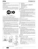
ú

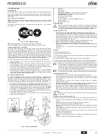
ek. 15 - Ba

÷

lant

Õ

 terminaline eri

ú

im

3.6 Bacaya ba

÷

lant

Õ

Bacaya ba

÷

lant

Õ

 borusunun çap

Õ

, geri-ak

Õ

ú

-önleme cihaz

Õ

n

Õ

n (rüzgar kesici) ba

÷

lant

Õ

 bo-

rusununkinden daha küçük olmamal

Õ

d

Õ

r. Geri-ak

Õ

ú

 önleme cihaz

Õ

ndan ba

ú

layarak, dikey

kesit de

÷

eri en az yar

Õ

m metre uzunlu

÷

unda olmal

Õ

d

Õ

r. Baca ba

÷

lant

Õ

lar

Õ

n

Õ

n ve ba

÷

lant

Õ

borular

Õ

n

Õ

n ebat ve montaj

Õ

 ile ilgili olarak mevcut standartlara riayet edilmelidir.

Geri ak

Õ

ú

 önleme cihaz

Õ

n

Õ

n duman ç

Õ

k

Õ

ú

 çap

Õ


ú

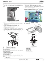
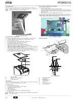
ek. 22 - 

ú

ek. 23 k

Õ

sm

Õ

nda belirtilmi

ú

tir.

8

9

10

11

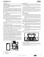
A

Содержание PEGASUS D

Страница 1: ...E E LA MANUTENZIONE ES INSTRUCCIONES DE USO INSTALACI N Y MANTENIMIENTO TR KULLANMA KURULUM VE BAK M TALIMATLAR EN INSTRUCTIONS FOR USE INSTALLATION AND MAINTENANCE FR INSTRUCTIONS D UTILISATION D INS...

Страница 2: ...a digitale con funzionalit avanzate di termoregolazione A La caldaia predisposta per il collegamento ad un bollitore esterno per acqua calda sanitaria opzionale In questo manuale tutte le funzioni re...

Страница 3: ...e modificarla con i tasti sanitario part 1 e 2 fig 1 Regolare la curva desiderata da 1 a 10 secondo la caratteristica fig 11 Regolando la curva a 0 la regolazione a temperatura scorrevole risulta disa...

Страница 4: ...e di acqua calda sanitaria Effettuare gli allacciamenti idraulici secon do lo schema fig 14 pompe e valvole di non ritorno devono essere fornite a parte Effettuare collegamenti elettrici come indicato...

Страница 5: ...golazione della pressione 4 2 Messa in servizio B La messa in servizio deve essere effettuata da Personale Qualificato e di sicura qualificazione Verifiche da eseguire alla prima accensione e dopo tut...

Страница 6: ...chiusura della camera fumi 3 Scovolo 7 Tappo per l analisi della combustione Analisi della combustione All interno della caldaia nella parte superiore dell antirefouleur stato inserito un punto di pr...

Страница 7: ...po l inter vento del termostato fumi il funzionamento della caldaia viene impe dito per 20 minuti Contatto termostato fumi aperto Verificare il termostato Cablaggio interrotto Verificare il cablaggio...

Страница 8: ...80 4x2 80 Pressione gas alimentazione G20 mbar 20 20 20 Pressione max valle valvola gas G20 mbar 15 13 15 Pressione min valle valvola gas G20 mbar 2 5 2 5 2 5 Portata gas max G20 m3 h 2 68 3 69 5 24 P...

Страница 9: ...82 Elettrodo rilevazione 126 Termostato fumi 130 Circolatore sanitario opzionale 138 Sonda esterna non fornito 139 Unit ambiente non fornito 246 Trasduttore di pressione 278 Sensore doppio Sicurezza...

Страница 10: ...n effettuato a cura dell azienda inosservanza delle istruzioni e delle avvertenze previste dall azienda produttrice e riportate sui manuali di utilizzo a corredo del prodotto errata installazione o in...

Страница 11: ...gua sanitaria descritas en este manual son v lidas s lo si el acumulador sa nitario opcional est conectado como se indica en sec 3 3 2 2 Panel de mandos fig 1 Panel de control Leyenda 1 Tecla 2 Tecla...

Страница 12: ...1 Si se elige la curva 0 la regulaci n con temperatura adaptable queda desactivada fig 9 Curva de compensaci n Si se pulsan las teclas de la calefacci n 3 y 4 fig 1 se accede al desplazamiento paralel...

Страница 13: ...ca de la caldera puede controlar un acumulador exterior para la pro ducci n de agua caliente sanitaria Realizar las conexiones hidr ulicas seg n el esque ma fig 14 las bombas y las v lvulas antirretor...

Страница 14: ...ene que ser efectuada por personal cualificado Con troles que se han de efectuar durante el primer encendido tras las operacio nes de mantenimiento que exigen desconectar la caldera y despu s de toda...

Страница 15: ...e de la c mara de humos 3 Cepillo 7 Tap n para el an lisis de la combusti n An lisis de la combusti n Dentro de la caldera en la parte superior del cortatiro hay un punto de toma de humo 7 fig 19 Para...

Страница 16: ...s la cual la caldera queda bloqueada durante 20 segundos Contacto del termostato de humos abierto Controlar el termostato Cableado interrumpido Controlar el cableado Chimenea mal dimensio nada u obstr...

Страница 17: ...taci n gas G20 mbar 20 20 20 Presi n m xima despu s de la v lvula de gas G20 mbar 15 13 15 Presi n m nima despu s de la v lvula de gas G20 mbar 2 5 2 5 2 5 Caudal m ximo de gas G20 m3 h 2 68 3 69 5 24...

Страница 18: ...do 82 Electrodo de detecci n 126 Termostato de humos 130 Bomba de circulaci n del agua sanitaria opcional 138 Sonda exterior no suministrada 139 Unidad ambiente no suministrada 246 Transductor de pres...

Страница 19: ...go de los componentes siendo por cuenta del usuario la mano de obra y el desplazamiento Cuerpo de las calderas de chapa Un a o Cuerpo de las calderas de hierro fundido Un a o cada elemento Cuerpo de c...

Страница 20: ...ayarlama fonksiyonlar na sahip dijital aray zl bir mikroi lemcidir A Kombi s cak musluk suyu retimi i in harici bir s t c kazana ba lanmak zere tasarlanm t r opsiyonel Bu kullan m k lavuzundaki s cak...

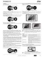
Страница 21: ...ak k s m 1 ve 2 ek 1 de i tirilmesi m mk nd r E riyi 1 ile 10 saniye aras nda istedi iniz gibi ayarlay n z ek 11 E ri 0 a ayarland nda s cakl k ak ayarlamas devre d kal r ek 9 Kompenzasyon e risi Is t...

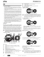
Страница 22: ...ap n z pompalar ve geri d n valflar ayr ca tedarik edilmelidir A a dakiler ger ekle tiriniz cap 5 4 k sm ndaki elektrik emas nda g sterilen elektrik ba lant lar Bir FERROLI sen s r n n kullan lmas ger...

Страница 23: ...Kalifiye Personel ve yeterlili e sahip ki iler ta raf ndan yap lmal d r lk al t rma an nda ve sistemden ba lant n n kesilmesi veya emniyet cihazlar nda ya da kombinin di er aksamlar nda bir bak m i le...

Страница 24: ...1 Muhafaza kapa 2 Duman odas kapatma plakas 3 F r a 7 Yanma analizi t pas Yanma analizi Dumanlar n rneklemesi amac yla bir nokta kombinin i erisinde geri ak nleme cihaz n n st k sm nda bulunmaktad r k...

Страница 25: ...ostat n n konta a kt r Termostat kontrol ediniz Kablolarda kopukluk var Kablo tesisat n kontrol ediniz Bacan n ebatlar yanl t r veya t kal durumdad r Duman kanal n de i tiriniz A06 Ate leme a amas nda...

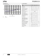
Страница 26: ...lar G20 n x 2x2 80 3x2 80 4x2 80 Besleme gaz bas nc G20 mbar 20 20 20 Gaz G20 valf y n nde maks bas n mbar 15 13 15 Gaz G20 valf y n nde min bas n mbar 2 5 2 5 2 5 Maks gaz k G20 m3 s 2 68 3 69 5 24...

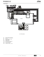
Страница 27: ...elektrotu 126 Duman termostat 130 Musluk suyu devir daim pompas opsiyonel 138 Harici sens r cihazla birlikte verilmez 139 Oda nitesi cihazla birlikte verilmez 246 Bas n d r c 278 ift sens r Emniyet Is...

Страница 28: ...ranged for connection to an external storage tank for hot water production optional In this manual all the functions relevant to domestic hot water production are only active with the optional hot wat...

Страница 29: ...d 2 fig 1 Adjust the required curve from 1 to 10 according to the characteristic fig 11 By setting the curve to 0 sliding temperature adjustment is disabled fig 9 Compensation curve Press the heating...

Страница 30: ...Carry out the plumbing connections according to the diagram fig 14 pumps and non return valves must be supplied separately Carry out electrical connections as shown in the wiring diagram incap 5 4 A...

Страница 31: ...5 Protection cap 6 Pressure adjustment screw 4 2 Start up B System start up must be carried out by Qualified Personnel Checks to be made at first lighting and after all maintenance operations that in...

Страница 32: ...e brush 7 Combustion analysis plug Combustion analysis A point for sampling fumes has been included inside the boiler in the upper part of the anti backflow device detail 7 fig 19 To take the sample 1...

Страница 33: ...Vent the system F04 Fume thermostat acti vated after activation of the fume thermostat boiler operation is pre vented for 20 minutes Fume thermostat contact open Check the thermostat Wiring disconnect...

Страница 34: ...2x2 80 3x2 80 4x2 80 Gas supply pressure G20 mbar 20 20 20 Max pressure downstream of gas valve G20 mbar 15 13 15 Min pressure downstream of gas valve G20 mbar 2 5 2 5 2 5 Max gas delivery G20 m3 h 2...

Страница 35: ...Detection electrode 126 Fume thermostat 130 DHW circulating pump optional 138 External probe not supplied 139 Room unit not supplied 246 Pressure transducer 278 Double sensor Safety Heating DSP05 7 6...

Страница 36: ...temp rature A Un ballon ext rieur option servant la production d eau chaude sanita ire peut tre raccord la chaudi re Dans ce manuel toutes les fonc tions relatives la production d eau chaude sanitaire...

Страница 37: ...t ristique fig 11 Si la courbe est r gl e sur 0 le r glage de la temp rature volutive est d sactiv fig 9 Courbe de compensation Appuyer sur les touches chauffage rep 3 et 4 fig 1 pour passer au d plac...

Страница 38: ...eau chaude sanitaire La carte lectronique de l appareil est pr vue pour la gestion d un ballon externe pour la production d eau chaude sanitaire Effectuer les raccordements hydrauliques selon le sch m...

Страница 39: ...ce B La mise en service doit tre effectu e par du personnel qualifi disposant du savoir faire et de l expertise n cessaires V rifications effectuer au premier allumage et apr s toutes les op rations d...

Страница 40: ...Bouchon pour l analyse de la combustion Analyse de la combustion Un point de pr l vement des fum es a t pr vu l int rieur de la chaudi re dans la partie sup rieure de l antirefouleur rep 7 fig 19 Pour...

Страница 41: ...ement du ther mostat s curit fum es apr s son d clenche ment le fonctionnement de la chaudi re est d sactiv pendant 20 minutes Contact de thermostat s curit fum es ouvert V rifier le thermostat C blag...

Страница 42: ...ur G20 nbre x 2x2 80 3x2 80 4x2 80 Pression d alimentation gaz G20 mbar 20 20 20 Pression maxi en aval vanne gaz G20 mbar 15 13 15 Pression mini en aval vanne gaz G20 mbar 2 5 2 5 2 5 D bit gaz maxi G...

Страница 43: ...lectrode de d tection 126 Thermostat fum es 130 Circulateur eau chaude sanitaire option 138 Sonde ext rieure non fournie 139 Unit d ambiance non fournie 246 Transducteur de pression 278 Capteur double...

Страница 44: ...19 20 21 22 23 24 25 26 27 2 3 2 B e sez 3 3 3 120 FH 5 FH on off 9 1 1 4 on off 9 1 1 5 9 1 B sez 3 3 eco comfort m o d e r e s e t bar 5 7 9 10 2 1 8 6 4 3 16 17 18 20 21 22 23 25 24 26 27 19 eco co...

Страница 45: ...1 0 F37 13 13 A 120 FH eco comfort m o d e r e s e t eco bar eco comfort m o d e r e s e t eco bar eco comfort m o d e r e s e t eco bar ECO COMFORT Eco nomy 7 1 Comfort 7 1 20 30 40 50 60 70 80 90 8...

Страница 46: ...U cod 3540U171 06 2012 Rev 00 3 3 1 3 2 A 3 3 B cap 5 1 25 Fr 1 F 10 CaCO3 15 F 236 88 B 6 C 14 cap 5 4 FERROLI 14 8 9 10 11 3 4 B 25 B 3 5 B Y 3 3A 2 B HAR H05 VV F 3x0 75 2 8 B 230 A 15 3 6 0 5 22 2...

Страница 47: ...16 TEST TEST TEST 15 PEGASUS D 17 cap 5 2 1 5 17 2 2 17 3 6 17 cap 5 2 4 2 3 G20 G25 G30 G31 1 cap 5 3 2 3 17 G20 G25 D 17 G30 G31 E 17 3 4 17 A B C D G20 G25 E G30 G31 1 2 3 4 5 6 4 2 B 1 17 120 FH...

Страница 48: ...PEGASUS D 48 RU cod 3540U171 06 2012 Rev 00 18 B 18 19 19 1 2 3 7 7 19 1 2 3 4 5 TEST 6 10 15 7 A 20 20 21 1 2 3 4 5 6 7 8 3 2 1 7 3 3 4 mm 5 4 8...

Страница 49: ...11 44 126 246 273 275 A01 A02 A03 F04 20 A06 F10 1 F14 2 i F34 170 F35 F37 F39 F40 o A41 F42 F47 A48 A49 400 850 246 44 275 273 44 275 615 70 10 7 111 181 582 261 37 10 11 7 112 109 126 500 850 246 4...

Страница 50: ...2 P Pmax 80 60 C 90 9 91 7 90 9 30 91 3 91 5 91 6 92 42 CE NOx 2 2 2 G20 x 2 x 2 80 3 x 2 80 4 x 2 80 G20 20 20 20 G20 15 13 15 G20 2 5 2 5 2 5 G20 3 2 68 3 69 5 24 G20 3 1 07 1 58 2 08 G31 x 2 x 1 75...

Страница 51: ...1 82 126 130 138 139 246 278 DSP05 7 6 5 4 3 2 1 11 10 9 8 7 6 5 4 3 2 1 T1 T2 X7 7 6 5 4 3 2 1 6 5 4 3 2 1 X5 F1 F2 X1 X2 X4 X3 X6 X8 X10 2 1 T T 278 GND 5V OUT 246 L N 230V 50Hz 138 139 72 L N 4 5 6...

Страница 52: ...9 10 16 17 18 19 20 21 22 23 24 25 26 27 Estate 2 3 2 B i i sez 3 3 i i i i i 3 i 120 FH i 5 i FHI on off 9 1 1 4 i i i i on off i 9 1 1 5 i i ON OFF 9 1 B i i i i i i i i sez 3 3 eco comfort m o d e...

Страница 53: ...10 10 1 i i i i i 11 12 i i A i i i i i i 1 5 1 1 i 1 0 i i i i i F37 13 13 A i i i i 120 FH eco comfort m o d e r e s e t eco bar eco comfort m o d e r e s e t eco bar eco comfort m o d e r e s e t e...

Страница 54: ...i i CaCO3 i i i i i i i 15 F I i i 236 88 B i i i i i i 6 C i i i i i i i i i 14 i cap 5 4 FERROLI i i i i i i i 14 i i 8 9 10 i 11 3 4 B i i i i i i i i i i i i i i i 25 i i i i i i i i i i i i i i...

Страница 55: ...5 17 2 i i 2 17 i 3 i 6 17 i i cap 5 2 4 i i i i i i 2 3 i i i i i G20 G25 G30 G31 1 i cap 5 3 2 i i 3 17 i G20 G25 D 17 G30 G31 E 17 3 i i i 4 17 A B C i D G20 G25 E G30 G31 1 2 i 3 4 5 6 4 2 B i i i...

Страница 56: ...i i i 19 i i i i i i i i i i i i i i i i i i i i i i i i i i 19 1 2 i i 3 7 i i i i i i i 7 19 1 i i 2 i i i i 3 i i i i 4 5 i TEST 6 10 15 7 A i i i i i i i i i i i i i i i i i i i 20 i i i i i i i i...

Страница 57: ...PEGASUS D 45 7 10 11 44 126 246 273 275 A01 A02 A03 F04 20 A06 F10 1 F14 2 F34 170 F35 F37 F39 F40 A41 F42 F47 A48 A49 400 850 246 44 275 273 44 275 615 70 10 7 111 181 582 261 37 10 11 7 112 109 126...

Страница 58: ...2 P i i i Pmax 80 60 C 90 9 91 7 90 9 i i i 30 91 3 91 5 91 6 92 42 EEC NOx 2 2 2 G20 x 2x2 80 3x2 80 4x2 80 G20 20 20 20 G20 15 13 15 G20 2 5 2 5 2 5 G20 3 2 68 3 69 5 24 G20 3 1 07 1 58 2 08 G31 x...

Страница 59: ...1 82 126 130 138 139 246 278 DSP05 7 6 5 4 3 2 1 11 10 9 8 7 6 5 4 3 2 1 T1 T2 X7 7 6 5 4 3 2 1 6 5 4 3 2 1 X5 F1 F2 X1 X2 X4 X3 X6 X8 X10 2 1 T T 278 GND 5V OUT 246 L N 230V 50Hz 138 139 72 L N 4 5 6...

Страница 60: ...ettiva Compatibilit Elettromagnetica 2004 108 Presidente e Legale rappresentante Cav del Lavoro Dante Ferroli IT Uygunluk beyani malat i FERROLI S p A Adres Via Ritonda 78 a 37047 San Bonifacio VR bu...

Страница 61: ...8 Dante Ferroli RU D claration de conformit Le constructeur FERROLI S p A Adresse Via Ritonda 78 a 37047 San Bonifacio VR d clare que cet appareil est conforme aux directives CEE ci dessous Directives...

Страница 62: ......

Страница 63: ......

Страница 64: ...FERROLI S p A Via Ritonda 78 a 37047 San Bonifacio Verona ITALY www ferroli it...

Отзывы: