background image

15

MODEL F80A

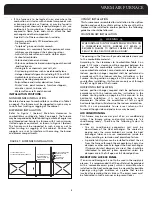
SETTING THE MANIFOLD (Outlet) GAS PRESSURE
(F92-1003 36G Valve Pressure Check Kit)

1.

Shut off the gas upstream of valve and move valve
switch to  “OFF”.

2.

Using the 3/32 inch hex wrench that is included in the
valve pressure check kit, rotate outlet pressure tap
screw one revolution counter-clockwise. 

3.

Attach the 5/16 inch hose that is included in the valve
pressure check kit to the outlet pressure boss of the
valve.  Hose should overlap boss 3/8 inch.

4.

Connect 5/16 inch side of connector that is included in
the valve pressure check kit to the hose on outlet boss.
Connect 1/4 inch side of connector to manometer hose. 

5.

Turn on gas supply to valve and move valve switch to
the “ON” position. 

6.

Turn on furnace following manufacturer’s instructions.

7.   Using a leak detection solution check for leaks at hose

connections. 

Figure 8: White-Rodgers Gas valve

DANGER

A TRAINED, QUALIFIED TECHNICIAN MUST DO ALL

REGULATOR ADJUSTMENTS. IMPROPER MODIFICATIONS
OR ADJUSTMENTS CAN RESULT IN FIRE OR EXPLOSION
CAUSING PROPERTY DAMAGE, SEVERE PERSONAL
INJURY OR LOSS OF LIFE.

In some circumstances, high inlet pressure can be remedied
with the use of an inline appliance regulator. If an inline
appliance regulator is used, ensure that it has the capacity
to adequately handle the gas volume required by the
furnace and any other appliances receiving gas from the
header serving the furnace.

ELECTRICAL SPECIFICATIONS

Before proceeding with the electrical connections, ensure
that the available electrical supply is compatible with the
voltage, frequency, and phase listed on the appliance rating
plate.

All furnaces are rated 120 VAC, 60 Hz, 1 phase. The
amperage rating is indicated on the furnace rating plate.

Each furnace requires a dedicated overcurrent device either
a circuit breaker or a Type D, time delay fuse. It is
permissible to connect furnace accessories such as
humidifier transformers, condensate pumps and electronic
air cleaners. If adding accessory equipment to the furnace
circuit, ensure that the combined amperages listed on the
appliance rating plates do not exceed the rating of the over
current device.

DANGER

SHUT OFF ELECTRICAL POWER AT THE FUSE BOX OR
SERVICE PANEL BEFORE MAKING ANY ELECTRICAL
CONNECTIONS. FAILURE TO DO SO CAN CAUSE
ELECTRICAL SHOCK RESULTING IN PERSONAL INJURY OR
LOSS OF LIFE.

DANGER

SHUT OFF GAS AND FIX LEAKS IMMEDIATELY BEFORE
PROCEEDING.

Outlet
Pressure
Boss

Inlet
Pressure
Boss
(Optional)

Regulator
Vent

On/Off Switch

Regulator
Adjustment

Connection
Terminals

8.

Read manometer.  This reading is the system
outlet/supply pressure. 

9.

Follow manufacturer’s instructions to adjust outlet
/supply pressure, if necessary.

10. Shut off gas supply upstream of valve and move the

valve switch to the “OFF” position.

11.   Remove manometer and hose from outlet boss.
12. Turn outlet pressure tap screw clockwise to seal the

pressure point using the supplied hex wrench.  Tighten
to 13 in-lbs. minimum.

13. Turn on gas supply to valve and move valve switch to

the “ON” position.

14. Turn on furnace following manufacturer’s instructions.
15.   Using leak detection solution check for leaks at outlet

pressure tap.  Shut off gas and fix all leaks immediately
before proceeding.

If problems were encountered with obtaining enough
pressure on the manifold, first examine the gas piping
system to ensure that it is correctly sized. Pipe sizing is
specified in ANSI Z223.1 / NFPA 54 in the U.S., or the B148
Natural Gas and Propane Installation Code in Canada. 

CHECKING THE SUPPLY (Inlet) GAS PRESSURE (F92-1003
Valve Pressure Check Kit)

Check inlet pressure following steps 1 through 15 above
using the inlet/supply pressure tap boss.

Содержание F80A

Страница 1: ...DIMENSIONS 5 DUCTWORK 6 DETERMING COMBUSTION AIR 7 FURNACE VENTING 8 GAS SUPPLY 12 CONVERSIONS 13 HIGH ALTITUDE AIRFLOW SPECIFICATION TABLES 14 ELECTRICAL SPECIFICATIONS 15 START UP PROCEDURES SEQUEN...

Страница 2: ...ated by the furnace to areas outside the space containing the furnace the return air shall also be handled by duct s sealed to the furnace casing and terminating outside the space containing the furna...

Страница 3: ...sociation 1515 Wilson Boulevard Arlington VA 22209 703 841 8400 National Fire Protection Association 1 Batterymarch Park Quincy MA 02269 9101 617 770 3000 Canadian Gas Association Suite 1 243 Consumer...

Страница 4: ...em An undersized return air system will prevent sufficient quantities of air from reaching the supply air system properly sized or otherwise and will consequently reduce the service life of the furnac...

Страница 5: ...pports so as not to interfere with accessing the burner and blower compartments The opening in the floor must provide adequate clearances to the combustible material According to the Clearances to Com...

Страница 6: ...E AREA AROUND THE FURNACE MUST BE KEPT CLEAR AND FREE OF ALL COMBUSTIBLE MATERIALS INCLUDING GASOLINE AND OTHER FLAMMABLE VAPORS AND LIQUIDS PLACEMENT OF COMBUSTIBLE MATERIALS ON AGAINST OR AROUND THE...

Страница 7: ...UCING DEVICE SUCH AS A FIREPLACE INSERT STOVE ETC DOING SO MAY RESULT IN FIRE CARBON MONOXIDE POISONING EXPLOSION PERSONAL INJURY LOSS OF LIFE OR PROPERTY DAMAGE CAUTION DO NOT USE THE REAR PANEL AS A...

Страница 8: ...gs one within 12 inches of the ceiling and the other within 12 inches of the floor The air openings must be sized based on whether the combustion and ventilation air is being taken from indoors or out...

Страница 9: ...NFPA 54 National Fuel Gas Code in the United States or B149 Natural Gas and Propane Installation Code in Canada and within the requirements of the codes of the local authority having jurisdiction Refe...

Страница 10: ...h joint to prevent sagging Horizontal segments must slope upward from the furnace to vent or chimney with a minimum 1 4 inch per foot When the vent tables from ANSI 223 1 NFPA 54 or B149 permit more t...

Страница 11: ...connector segments together with a minimum of three sheet metal screws per joint Secure the vent connector to the furnace collar with a minimum of three sheet metal screws Type B vent connectors do n...

Страница 12: ...EDICATED VENTING Figure 7 below shows a good method to permit dedicated venting making use of B Vent within a masonry chimney When using this method provide support for the B Vent IMPORTANT maintain a...

Страница 13: ...there is no blockage restriction leakage corrosion collapsed materials such as fallen bricks or any other deficiency that could lead to an unsafe condition 3 Insofar as practical duplicate winter oper...

Страница 14: ...ntity of dish detergent with water and daubing it onto the gas piping and connections PURGING GAS LINES NATURAL TO L P GAS This series furnace is manufactured as a natural gas sea level appliance It m...

Страница 15: ...5 mm 1 20 mm 135 2000 4500 121 500 97 200 1 90 mm 1 15 mm 0 2000 135 000 108 000 1 95 mm 1 20 mm 2000 3000 118 800 95 040 1 83 mm 1 13 mm 3000 4000 113 400 90 720 1 79 mm 1 10 mm 4000 5000 108 000 86...

Страница 16: ...ce requires a dedicated overcurrent device either a circuit breaker or a Type D time delay fuse It is permissible to connect furnace accessories such as humidifier transformers condensate pumps and el...

Страница 17: ...to the right hand side The junction box contains a BLACK wire to be connected with L1 hot a WHITE wire to be connected with L2 the Neutral and a GREEN wire to be connected to the ground Use good qual...

Страница 18: ...gin again at Step 4 above If the flame sensing signal is lost more than 5 times during a furnace cycle the gas valve will close and the ignition sequence goes into a 5 second postpurge the induced blo...

Страница 19: ...and the air filter or filters are in place determine if the airflow is correct 1 Insert a duct thermometer in the supply air duct The thermometer should be placed as close as practical to the furnace...

Страница 20: ...ower assembly to slide into blower rails Push blower assembly towards back of furnace ensuring blower assembly is correctly placed in blower rails Insert blower shroud on the front of the blower housi...

Страница 21: ...ture and drapes so that the supply air registers and return air grilles are unobstructed 5 If you have a perimeter duct system ideally the warm air should bathe the cold exterior walls Avoid the use o...

Страница 22: ...ft blue and not impinging on the heat exchanger CAUTION Label all wires prior to disconnection when servicing controls Wiring errors can cause improper and dangerous operation Always verify proper ope...

Страница 23: ...TRIAL FOR IGNITION CIRCULATING AIR FAN ON AFTER DELAY FLAME SENSE LOST MAIN VALVE CLOSES THERMOSTAT CALL FOR HEAT ENDS MAIN VALVE CLOSES COMBUSTION AIR BLOWER OFF AFTER POST PURGE CIRCULATING AIR FAN...

Страница 24: ...23 MODEL F80A 50V51 250...

Страница 25: ...ne voltage to L1terminal of must be 120 volts with reference to furnace chassis 2 Furnace must be reliably connected to earth ground 3 Induced blower moving main burner flame away from the flame senso...

Страница 26: ...25 MODEL F80A R R 3 FACTORY SETTING...

Страница 27: ...O IF YOU SMELL GAS DO NOT TRY TO LIGHT ANY APPLIANCE DO NOT TOUCH ANY ELECTRICAL SWITCH DO NOT USE ANY PHONE IN YOUR BUILDING LEAVE THE BUILDING IMMEDIATELY IMMEDIATELY CALL YOUR GAS SUPPLIER FROM A P...

Страница 28: ...nside air from outdoors from an attic or crawl space If renovations are done be sure that air supply openings are not inadvertently covered over with insulation vapor barrier or similar construction m...

Страница 29: ...the next step 8 Gas valve Ensure that the Gas Valve Control is in the ON position see Figure 3 at right 9 Replace the burner access door ensuring that it is properly in place 10 Restore the electric...

Страница 30: ...the furnace All ductwork should be secured to the furnace and all ductwork should be solidly supported throughout the heating system The furnace should be well supported on a level floor or by the me...

Страница 31: ...operation points 5 and 9 will be ignored CAUTION THE FURNACE SHOULD BE OPERATED WITH ALL PANELS IN PLACE NEVER OPERATE THE FURNACE WITH THE BLOWER DOOR REMOVED EXCEPT FOR SERVICE PURPOSES WARNING ALWA...

Страница 32: ...o Warm Air Furnace products Illustrations cover the general appearance of the units at the time of publication and the manufacturer reserves the right to make changes in design and construction at any...

Отзывы: