FEDCO MSD-160 Скачать руководство пользователя страница 23

MSD

TM

 Series

© Copyright 2018 Fluid Equipment Development Company | www.fedco-usa.com

23

 -

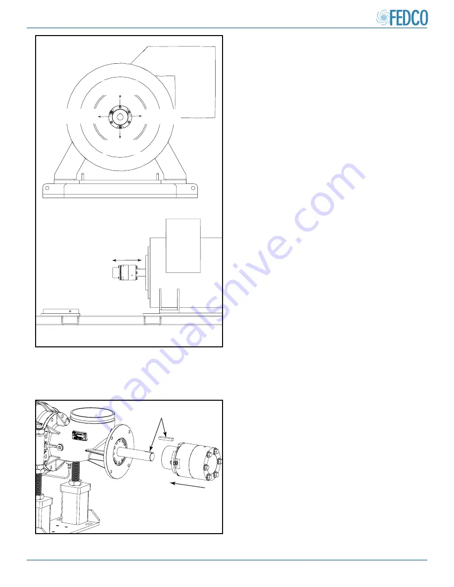
Figure 34 - Install Dropout Coupling On Pump 

Shaft

ANTI-SEIZE

8. Apply a system compliant anti-seize com-

pound and slide the dropout coupling over 

the pump shaft with the pump shaft key.

NOTES: 

The rounded end of the key must be 

placed in the rounded end of the keyway.

Figure 33 - Check Dropout Coupling Fit On 

Shaft


NO

MOVEMENT


NO

MOVEMENT


NO

MOVEMENT


NO

MOVEMENT

7. Inspect the dropout coupling’s radial and 

axial fit. It should be tight with no visible 

radial movement and slide smoothly on and 

off the motor shaft

Pump Assembly Continued

SMOOTH MOVEMENT

Содержание MSD-160

Страница 1: ...l 08 160 XXXXXX 0 INSTALLATION OPERATION MANUAL www fedco usa com ONE COPY OF THIS MANUAL MUST REMAIN WITH THE EQUIPMENT AT ALL TIMES English Version Models MSD 160 MSD 200 MSD 350 MSD 400 MSD 270 MSD...

Страница 2: ...nvironmental Management System EMS to better protect our environment 3 FEDCO achieved ISO 14001 registration in September 2017 CE Stamp CE marking confirms that specific products are in compliance wit...

Страница 3: ...s maintenance and lo gistics issues associated with oil or grease lubricated bearing systems We offer three materials of construc tion Duplex SS Super Duplex SS and 316 SS We design fluid machines to...

Страница 4: ...cations 16 Pump Assembly 17 Horizontal Motor Installation 17 Flexible Coupling Check 18 Horizontal Motor Installation No Motor Adapter 21 Vertical Motor Installation 25 Initial Pump Alignment 31 Final...

Страница 5: ...complete please contact your shipping company or a FEDCO representative before proceeding 6 7 8 9 10 11 12 13 5 4 3 2 1 14 15 Figure 1 Pump Assembly External Components Item Description Item Descripti...

Страница 6: ...ase of turning Check for axial movement 3 Seal Check Prime MSD with clean water and allow the O rings to soak for 1 hr before start up Check for leaks Motor Storage Requirements Specific conditions ar...

Страница 7: ...s if pump inlet pressure exceeds 150 psi 10 bar Motors are selected according to equipment operating requirements A flexible coupling al lows the pump shaft to float within the coupling eliminating th...

Страница 8: ...st bearing for the pump This unique design uses patented WATER BEARING technology which allows feed water to cool and lubricate the balance disc As the motor rotates the pump pressure differ ences act...

Страница 9: ...of causing SEVERE PERSONAL INJURY OR DEATH DANGER WARNING CAUTION ELECTRICAL HAZARD PUNCTURE HAZARD Installation Procedures Warnings and Safety Precautions Safety practices and precautions for the ope...

Страница 10: ...ed without the approval of a FEDCO representative WARNING NEVER operate the pump equipment below the minimum flow rate when dry without priming without proper guards and safety devices installed with...

Страница 11: ...C AMB CONT USABLE AT 208V 8 1 A DE 6205 ODE 6203 TEFC SN FO603113416 Motor Requirements ELECTRICAL HAZARD Wiring of the motor shall be completed in conformance with all local electrical codes All EU c...

Страница 12: ...unit nameplate Mechanical lifting equipment must be used MSD pumps can be lifted using approved lifting straps and suitable lifting equipment The straps must be installed every four 4 stages without d...

Страница 13: ...ed according manufacturers instructions Do not lift the pump and motor by the motor eyebolt The eyebolt is used for lifting the motor only NOTES Do not lift pump and base plate with the motor on the b...

Страница 14: ...ment Whenever possible all components should be lifted and moved separately for safety Do not lift the pump up by the shaft If the unit is lifted by the shaft damage may occur Lifting and handling of...

Страница 15: ...ment or from torque reaction forces during pump operation 1 1 2 2 3 4 2 5 5 Item Description Item Description 1 Motor mounting 4 to 6 depending on motor 4 Precision leveling foot mounting plate 2 Late...

Страница 16: ...6 inches 15 cm on each side from the pump and motor Make sure the concrete is com pletely dry and level before installing any ma chinery Make sure anchor bolts and shims are properly sized and install...

Страница 17: ...on were one of the motor frame feet are not in flat contact with the mounting base If not properly shimmed when the bolt is tightened the motor frame will distort FEDCO does not supply mo tor shims Ho...

Страница 18: ...n screws and remove the two coupling guards This allows better access to view the coupling alignment in later steps Figure 22 Direction Arrows On Motor Adapter 3 Prior to pump installation energize th...

Страница 19: ...the pump shaft with the pump shaft key NOTES The rounded end of the key must be placed in the rounded end of the keyway Figure 25 Check Flex Coupling Fit On Shaft NO MOVEMENT NO MOVEMENT NO MOVEMENT...

Страница 20: ...nd axial fit It should have little or no movement and be slightly more loose than the motor shaft fit It should also slide smoothly on and off the pump shaft 10 Once proper flexible coupling fit on bo...

Страница 21: ...m soft foot Soft foot is a condition were one of the motor frame feet are not in flat contact with the mounting base If not properly shimmed when the bolt is tightened the motor frame will distort FED...

Страница 22: ...preform coupling alignment in later steps 3 Prior to pump installation energize the motor to determine the direction of motor rotation The correct rotation is indicated by arrow on theMSDbrandingplate...

Страница 23: ...upling over the pump shaft with the pump shaft key NOTES The rounded end of the key must be placed in the rounded end of the keyway Figure 33 Check Dropout Coupling Fit On Shaft NO MOVEMENT NO MOVEMEN...

Страница 24: ...t and be slightly more loose than the motor shaft fit It should also slide smoothly on and off the pump shaft 10 Once proper flexible coupling fit on both shafts has been obtained remove the drop out...

Страница 25: ...ntinued Figure 36 Direction Arrows On Motor Adapter Vertical Motor Installation 1 Prior to pump installation energize the motor to determine the direction of motor rotation The correct rotation is ind...

Страница 26: ...coupling guards This allows better access to view the coupling alignment Figure 38 Check Flex Coupling Fit On Shaft 4 Inspect the flexible coupling radial and axial fit It should be tight with no visi...

Страница 27: ...g Fit On Shaft APPLY SYSTEM COMPLIANT ANTI SEIZE COMPOUND Figure 40 Check Flex Coupling Fit On Shaft NOTES Apply system compliant anti seize compound on the motor shaft and in the pump shaft keyway an...

Страница 28: ...t past the end of the motor shaft 11 Install the flexible coupling set screws and tighten NOTES Set screws are only on the motor side of the flexible coupling No set screws should be installed on the...

Страница 29: ...pump shaft into the flex coupling Pilot the pump base bore and align the motor mounting holes with the holes in the pump base Pump Assembly Continued Figure 44 Rotate Shafts For Coupling Alignment NO...

Страница 30: ...Installation 15 Install coupling guards and secure screws NOTES There is no initial or final pump align ment procedures for vertically mounted MSD units Proceed to Pump Piping Connections section Figu...

Страница 31: ...e Final Pump Alignment procedure is used to finalize the align ment and assembly with the coupling installed Pump vertical alignment is adjusted by rotating the precision leveling foot adjustment nuts...

Страница 32: ...ure be low 1 Using the described Horizontal Lifting and Handling methods described in this manual place the MSD in it s horizontal mounting position 2 Completely loosen both top nuts on each of the pr...

Страница 33: ...motor adapter are properly aligned NOTES This step does not apply for units with no motor adapter Figure 52 Leveling Motor Adapter 4 Loosen the in line jacking bolt to bring the pump and motor adapter...

Страница 34: ...d the A B measured align ment gap if existent in the Start Up Record section of this manual A A B B NO YES A B A B Figure 55 Motor Adapter Top and Bottom Gap Figure 54 Precision Leveling Foot Adjustme...

Страница 35: ...ied in the Pump Alignment Specifications section of this manual NOTES Record the C D measured align ment gap if existent in the Start Up Record section of this manual NOTES Re check the inlet precisio...

Страница 36: ...disc pack Ensure that the motor shaft key does not slide out of place or project past the end of the motor shaft Figure 59 Installing Motor Shaft Key APPLY SYSTEM COMPLIANT ANTI SEIZE COMPOUND 2 Apply...

Страница 37: ...Apply system compliant anti seize com pound in the pump shaft keyway and install pump shaft key NOTES The rounded end of the pump shaft key must be placed in the rounded end of the keyway Figure 61 F...

Страница 38: ...ctions using the adjustment nuts at the inlet precision leveling foot FEELER GAGE Figure 65 Motor Adapter Gap Measurement Points 8 If a gap exists between the motor adapter and motor use feeler gauges...

Страница 39: ...re may be no gap between the motor and motor adapter NOTES These values should be identical with the C D values found in the Start Up Re cord section of this manual 11 Tighten all precision leveling f...

Страница 40: ...sing leveling foot and working backwards to wards the motor NOTES Tighten to torque specs specified in the Fastener Torque Specifications section of this manual Figure 70 Discharge Housing Precision L...

Страница 41: ...nd Initial Pump Alignment proce dure completed NOTES The following steps outline the dial indicator method If using the Reverse Indica tor or a Laser Alignment Tool Method retain alignment bushing unt...

Страница 42: ...ignment procedure 6 Using a straight edge align pump and motor shafts NOTES If necessary refer to Initial Pump Alignment to make adjustments Figure 76 Install Dropout Coupling On Motor Shaft 3 Fit the...

Страница 43: ...or Shaft Figure 80 Install Dropout Coupling On Pump Shaft 10 After dial indication and adjustments have been made reinstall the coupling hubs 11 The pump shaft end should be inset ap proximately 1 8 a...

Страница 44: ...TES Set screws are only on the motor side of the dropout coupling NO set screws should be installed on the pump shaft side of the cou pling 13 Join the motor hub with the dropout hub us ing hardware r...

Страница 45: ...tance under its own weight This determines the sag tolerance of a given dial indicator set up 1 Assemble a dial indicator set up similar to the one which will be used during the align ment procedure a...

Страница 46: ...curred repeat the Sag Test steps 1 through 4 EXAMPLE If the dial indicator registers a reading of 0 002 Multiply the negative read ing by negative one half or 0 5 This will give you a product of 0 001...

Страница 47: ...ge or inlet Pipe Coupling Connections Follow all manufacturer installation and torque specifications Align all piping carefully before installing couplings Make sure all seals seat correctly inside th...

Страница 48: ...2 5 1 36 0 26 21 6 6 625 168 3 0 0 10 0 2 5 1 5 0 17 14 8 8 625 219 1 0 0 10 0 2 5 0 50 0 14 11 10 10 750 273 0 0 0 10 0 2 5 0 40 0 11 9 12 12 750 323 9 0 0 10 0 2 5 0 34 0 09 7 Figure 93 Flexible Pip...

Страница 49: ...of 1 8 Flange faces must be no more than a maximum of 5 degrees from each other Take appropriate measures to compensate thermal expansion of the piping Measure and record the flange gaps in the Start...

Страница 50: ...e inlet side Outlet Piping The pump discharge piping should have a removable section of pipe such as a spool piece or elbow to allow the pump to slide forward for service Servicing the shaft seal wate...

Страница 51: ...d be positioned to drain to atmosphere or connected to a feed pipe with a pressure not exceeding 150 psi 10 bar WARNING Under no circumstances should the vent line be plugged A plugged vent line will...

Страница 52: ...e valve It is recommended that a pressure switch should be installed at the pump inlet to prevent pump operation if the feed pressure to the pump is below specifications MSD pumps are not equipped wit...

Страница 53: ...e valves and building walls For applications were a minimum noise level is required the system should be operated with the flow adjusted as close to optimum efficiency as possible Vibra tion may also...

Страница 54: ...X FEDCO will give you easy step by step instructions on how to proceed Visual Inspection Make sure all items are accounted for on the start up check list Inspect all piping and electrical connections...

Страница 55: ...al damage Inspect balance disc for damage Inspect HPSC vent line for restrictions if equipped Design parameters Pump not designed for operating conditions Pump vibration or noise Operating conditions...

Страница 56: ...ce Parts Kits chart on the following two pages of this manual Service Parts Kits Refer to the Service Parts Kits chart on the following two pages of this manual NOTES Please provide pump serial number...

Страница 57: ...ring X 16 Stage bushing anti roll pin X 17 Stage bushing X 18 Stage bushing O Ring X X 19 Stage bushing retaining ring X 20 Bearing holder 21 Bearing holder O Ring X X 22 Balance disc washer X 23 Bala...

Страница 58: ...elopment Company www fedco usa com 58 Figure 101 Service Parts Kits Components 1 2 3 4 5 6 7 8 9 10 11 12 13 14 15 16 17 18 19 20 21 22 23 24 25 26 27 28 29 30 31 32 33 34 35 36 34 38 39 37 40 12 14 4...

Страница 59: ...mpeller set screw MSD 160 MSD 200 9 5 N m 7 Lb ft Impeller set screw MSD 350 MSD 400 16 N m 12 Lb ft Mechanical seal cartridge screws 9 5 N m 7 Lb ft Vertical assembly stand brace bolts 134 N m 97 Lb...

Страница 60: ...wear irregularities torsional backlash running behavior and tightening torque refer to Flexible Coupling Check 3 Inspect for leaks damaged gaskets and condition of all pipe couplings 4 Wipe pump motor...

Страница 61: ...ced in accordance with the FEDCO warranty Use the following address to return parts ATTN Field Service Department FEDCO 800 Ternes Drive Monroe MI 48162 USA Additional Contact Information Tel 734 241...

Страница 62: ..._____ Suction Pressure to Pump _________________ Discharge Pressure _____________________ Drain flow rate high inlet pressure option only _________________________ VFD frequency Hz if used ___________...

Страница 63: ...Flow ____________________________ Suction Pressure to Pump _________________ Discharge Pressure _________________________ General Notes _______________________________________________________________...

Страница 64: ...________________________ VFD frequency Hz if used _________________ Voltage and Hz of power supply___________ Feed Flow ______________________________ Suction Pressure to Pump __________________ Disch...

Страница 65: ...____________________________ _____________________________________________________________________________ _____________________________________________________________________________ _______________...

Страница 66: ...om FEDCO USA FEDCO 800 Ternes Drive Monroe MI 48162 USA Telephone 1 734 241 3935 Fax 734 241 5173 Email sales fedco usa com FEDCO UAE Office 1910 Concord Tower P O Box 282102 Media City Dubai United A...

Отзывы: