Machine description- Decals
Relays
Relays
1. K1
Starting
12V 30A
1. K1
Starting
12V 30A
2. K2
Start, vibration, brake
12V 15A
2. K2
Start, vibration, brake
12V 15A
3. K22
Cooling fan, hydraulic system (Option)
12V 30A
3. K22
Cooling fan, hydraulic system (Option)
12V 30A
4. K20
Drive restriction relay
12V 10A
4. K20
Drive restriction relay
12V 10A
Fuses
Fuses
5. 7.5A
Start/stop valve
Fuel pump
Restriction relay
VBS relay
Vibration
5. 7.5A
Start/stop valve
Fuel pump
Restriction relay
VBS relay
Vibration
6. 15A
Horn
Backup alarm
Fan (Option)
6. 15A
Horn
Backup alarm
Fan (Option)
28
4812274432.pdf
2017-07-10
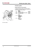
Electrical system
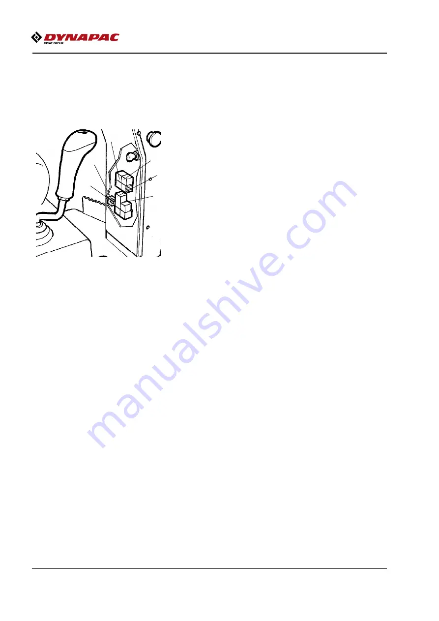
Relays and fuses on the machine
The figure shows the positions of the various fuses
and relays. The table below gives their amperage and
function. All fuses are flat pin fuses.
Fig. Control column
1
2
3
4
5
6
Содержание Dynapac CC900G
Страница 2: ......
Страница 16: ...Safety when operating 8 4812274432 pdf 2017 07 10 ...
Страница 20: ...Special instructions 12 4812274432 pdf 2017 07 10 ...
Страница 22: ...Technical specifications Noise Vibrations Electrical 14 4812274432 pdf 2017 07 10 ...
Страница 30: ...Machine description Decals 22 4812274432 pdf 2017 07 10 ...
Страница 42: ...Operation 34 4812274432 pdf 2017 07 10 ...
Страница 54: ...Operating instructions Summary 46 4812274432 pdf 2017 07 10 ...
Страница 56: ...Operating instructions Summary 48 4812274432 pdf 2017 07 10 ...
Страница 58: ...Preventive maintenance 50 4812274432 pdf 2017 07 10 ...
Страница 62: ...Maintenance Lubricants and symbols 54 4812274432 pdf 2017 07 10 ...
Страница 70: ...Maintenance Maintenance measures before use 62 4812274432 pdf 2017 07 10 ...
Страница 80: ...Maintenance 100h 72 4812274432 pdf 2017 07 10 ...
Страница 88: ...Maintenance 500h 80 4812274432 pdf 2017 07 10 ...
Страница 96: ...Maintenance 1000h 88 4812274432 pdf 2017 07 10 ...

