C
ONFIGURATION
C
OMMAND
S
ET
- F
IRMWARE
R
EVISION
2.4.0_
BETA
-
V
ERSION
1.0.0
3.2.25.1.1.9.2
IEEE.IOBOX<
index
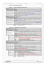
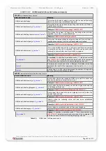
>.IN (Input states and events)
STATES
-
are checked every second
State notification code
Meaning
IEEE.IOBox<
index
>.IN.s<
in_index
>=low
True when the input port <
in_index>
from an I/O-BOX device goes low.
IEEE.IOBox<
index
>.IN.s<
in_index
>=high
True when the input port <
in_index>
from an I/O-BOX device goes high.
<
index
>
Identifies which I/O-BOX device caused an specific event. It is used as a
device identifier at the time of the event. The number of IEEE devices
(K I/O-BOX) connected to the MAMBOII limited to 6 from 0 .. 5.
-
NOTE: Both states will properly work only when the report mode
> from the Configuration parameter is set to
1
or
2
.
<
in_index
>
Identifies which input on the I/O-BOX changed its state. Depending on the
order option, it can be set to:
0 ... 3
if 16-pin MOLEX connector available.
0
or
4
if 8-pin connector (extension cable) available.
Pin designations for the 16-pin MOLEX and 8-pin connector are shown in
chapter 6.10.3.
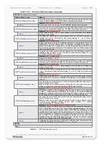
EVENTS
-
are evaluated just when the event occurs
Event notification code
Meaning
IEEE.IOBox<
index
>.IN.e<
in_index
>=redge Occurs when a rising-edge on the specified input <
in_index>
of the I/O-BOX
is triggered.
IEEE.IOBox<
index
>.IN.e<
in_index
>=fedge
Occurs when a falling-edge on the specified input <
in_index>
of the I/O-BOX
is triggered.
<
index
>
Identifies which I/O-BOX device caused a specific event. It is used as a
device identifier at the time of the event. The number of IEEE devices
(K I/O-BOX) connected to the MAMBOII is limited to 6 from 0 .. 5.
NOTE: Both events will properly work only when the report mode
<in_report_mode> from the Configuration parameter is set to
1
or
2
.
<
in_index
>
Identifies which input on the I/O-BOX caused the event. Depending on the
order option, it can be set to:
0
...
3
For I/O-BOX with 16-pin MOLEX connector.
0
or
4
For I/O-BOX with 8-pin extension cable.
Pin designations for the connectors are shown in chapter 6.10.3.
Table 43:
IOBOX Input states and events.
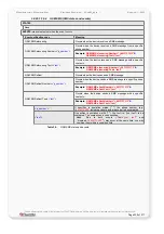
3.2.25.1.1.9.3
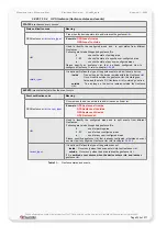
IEEE.IOBOX<
index
>.ANA (
Analogue Input states and events
)
STATES
-
are checked every second
State notification code
Meaning
IEEE.IOBox<
index
>.ANA.s<
aindex
>
<
comp
><
voltage
>
True when the comparison of both the current voltage on the analogue
input
<
aindex
>
and the user specified <
voltage
> is evaluated true.
Example:
IO.ANA.s1<12.25
<
index
>
Identifies which I/O-BOX device changed a specific state. It is used as a device
identifier at the time of the event. The number of IEEE devices (K I/O-
BOXes) connected to the MAMBOII is limited to 6 from 0 .. 5.
<
aindex
>
Identifies which input on the I/O-BOX changed its state. It can be set to
0
or
1
. Pin
designations for the connectors are shown in chapter 6.10.3.
To show correct voltages on the analog inputs, they have to be calibrated before
use. Pin designations for the connectors are shown in chapter 6.10.3.
<
comp
>
Compares two values and return a Boolean (True/False) value that represents the
result of the comparison. It can be set to =, !=, <, >, <= or >=.
<
voltage
>
it defines the value of voltage which can be set from 0 to 12 (number can be
represented with floating-point notation).
EVENTS
None
Table 44:
IOBOX Analogue Input states and events.
This confidential document is a property of FALCOM and may not be copied or circulated without previous permission.
Page 233 of 271


