


Cables
7.
CABLES
Motor fee
dback
cabl
es
· 222 ·
230
Ref.2003
QC-PDS
HARDWARE
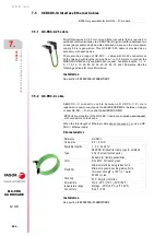
7.3.2 QC-EEC-FM7-X cable
The range of QC-EEC-FM7-
motor encoder feedback cables supplied by
FAGOR establishing the connection between the magnetic TTL encoder of
an FM7 spindle motor and QC-DR-
-F
drive controlling it. FAGOR
supplies them upon request and only with the connector on the end side of
the drive. The other end leads all drivers in the air (without a connector)
with each terminal crimped and numbered in its identification ring. The user
should perform the assembly on the body of the ELP-12V connector,
available as an accessory, on this end of the cable (engine side). Available
lengths: 3, 5, 10, 15, 20, 30 and 50 m.
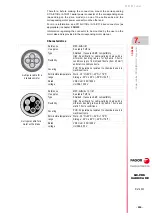
Characteristics
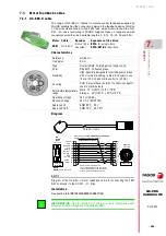
Diagram
Installation
See section,
8.6.1 MOTOR FEEDBACK CONNECTION
.
Motor Cable
Encoder Connector of the drive
FM7
QC-EEC-FM7-
Magnetic
TTL
E21A
for a single-drive
Reference
QC-EEC-FM7-
e approx.
8.5 mm
Type
Overall shield. Twisted pairs of copper wire.
Color
RAL 6018. Yellowish green.
Flexibility
High. Specially designed for controlling servo drives
with minimum bending radius for dynamic use 10x
e
(85 mm) and static use 5x
e (42.5 mm).
Covering
PUR. Polyurethane resistant to chemical agents
used in machine tools.
Permissible temperature
range
Work: -10°C/80°C (14°F/176°F)
Storage: -40°C/80°C (-40°F/176°F)
Operating voltage
30 V (UL/CSA)
Nominal voltage
30 V AC (EN 50395)
Approved UL
AWM 80°C - 30 V
Approved CSA
AWM 75°C - 30 V FT1
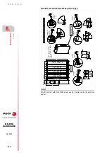
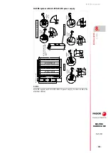
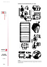
F. H7/2
Diagram of the QC-EEC-FM7-
motor feedback cable for connecting the FM7
magnetic TTL encoder to the QC-DR-
-F
drive.
R e a d y m a d e c a b l e
Q C - E E C - F M 7 - 0 3 / 0 5 / 1 0 / 1 5 / 2 0 / 3 0 / 5 0
L e n g t h i n m e t e r s ; c o n n e c t o r i n c l u d e d
1
7
6
5
4
3
1 1
1 2
2
P C B
P C C
T H S A
T H S B
+ 5 V D C
8
6
5
4
3
2
1
1 5
1 3
9
1 1
C a b l e 4 x 2 x 0 . 2 5 + 2 x 0 . 5
S i g n a l P i n
p i n s
f r o n t v i e w
0 . 5 m m ²
O v e r a l l s h i e l d . T w i s t e d p a i r s .
T h e o v e r a l l s h i e l d m u s t b e c o n n e c t e d t o
t h e m e t a l h o u s i n g a t t h e Q C - D R d r i v e e n d .
S L F - 0 1 T - P 1 . 3 E
( H D ,
S u b - D
M 1 5 )
P C A
4 0 m m
P C A
P C B
P C C
1 4 0 m m
1 0
y e l l o w / g r e e n
2 0 A W G
r i n g t o n g u e t e r m i n a l
M 5 , 2 0 A W G , 0 . 5 m m
2
0 . 5 m m ²
0 V D C
1
6
1 1
id
en
tif
ic
at
io
n
rin
g
nu
m
be
r
t o t h e d r i v e
Q C - D R
E 2 1 A
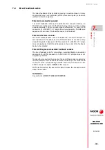
QC-EEC-FM7-
cable
INFORMATION.
Use the QC-EEC-FM7-
cable to ensure compliance with
Directive on Electromagnetic Compatibility EMC.
i
Содержание QC-PDS
Страница 1: ...DRIVE QC PDS Hardware manual Ref 2003...
Страница 6: ...6 I 6 Ref 2003 6 QC PDS HARDWARE This page intentionally left blank...
Страница 16: ...16 Ref 2003 16 Previous I QC PDS HARDWARE This page intentionally left blank...
Страница 18: ...18 Ref 2003 18 Previous II QC PDS HARDWARE This page intentionally left blank...
Страница 80: ...2 POWER SUPPLIES Power supplies 80 Ref 2003 QC PDS HARDWARE...
Страница 138: ...3 DRIVES Drives 138 Ref 2003 QC PDS HARDWARE...
Страница 174: ...4 AUXILIARY MODULES Auxiliary modules Ref 2003 174 QC PDS HARDWARE...
Страница 302: ...8 INSTALLATION Installation Ref 2003 302 QC PDS HARDWARE...
Страница 322: ...Connection diagrams 10 CONNECTION DIAGRAMS 322 Ref 2003 QC PDS HARDWARE 322 This page intentionally left blank...
Страница 366: ...12 COMMERCIAL MODELS Commercial models Ref 2003 QC PDS HARDWARE 366...
Страница 367: ...ANNEXES...
Страница 368: ...ANNEX A1...
Страница 383: ...ANNEX A2...
Страница 398: ...ANNEX A3...
Страница 418: ......
Страница 419: ......


