| English
6
CBC 242C PLUS - CBC 252C PLUS
IDENTIFICATION
1.
Trimmer head
2.
Bevel gear grease cap
3.
Bevel gear
4.
Cutting guard
5.
Shaft
6.
ON/OFF switch
7.
Throttle trigger
8.
Throttle trigger lockout
9.
Harness ring
10.
Cylinder cover
11.
Starter handle
12.
Fuel tank
13.
Choke lever
14.
Air filter cover
15.
Handlebar
16.
Locking nut
17.
Support cup
18.
Support flange
19.
Drive disc
20.
Handlebar clamp
21.
Socket spanner
22.
Harness
23.
Air purge
24.
Guard extension
25.
Blade
26.
Cutting Disc
GENERAL SAFETY RULES
Read this manual carefully before using the brush
cutter and take care of all safety instructions, in
order to prevent any injury and damage. Please
forward these safety instructions to any other
person who uses the brush cutter. Always use
your common sense to avoid all situations consid
-
ered beyond your capability. Do not hesitate to
contact with us if you have any questions about
the use of brush cutter. We will provide you with
advice as well as help, on how to use the brush
cutter safely.
PERSONAL PROTECTIVE EQUIPMENT
Always use personal protective equipment such
as safety glasses, helmet with visor, protective
gloves, protective boots and hearing protection.
SAFETY EQUIPMENT ON THE BRUSH CUTTER
Throttle trigger lockout
The brush cutter is equipped with a throttle trigger
lockout, in order to prevent accidental operation of
the throttle control. The throttle button is not able
to get pressed, unless the throttle trigger lockout
is being pressed first (photo 1). When the operator
releases the handle, the throttle and the throttle
lock must return to their original position, as well
as the engine speed must return to the idle speed.
ON/OFF switch
The switch is used to stop the operation of the
engine. Make sure that the switch is turned ON
before starting the engine; otherwise, the engine
will not be able to start.
Cutting guard
The guard is used to protect the operator from
getting in touch with the cutting equipment, as
well as to prevent small stones or other objects,
from being thrown towards him.
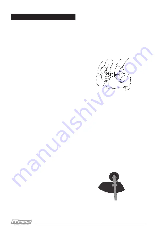
Quick release
The harness of the brush cutter is equipped with
an accessible quick release lock located at the
breast of the user, which is used as a safety fea
-
ture in order to throw away the machine, in the
event of fire (Fig. 1). Always check before using
the brush cutter that the quick release lock works
correctly.
CUTTING EQUIPMENT
Always use the recommended by the manufacturer cut
-
ting equipment (trimmer head and trimmer line). The
recommended size of trimmer line has been tested by
the manufacturer, to suit on the engine fitted on the
brush cutter. Small engines require small diameter of
trimmer line, compared to bigger engines which can be
fitted with bigger diameter of trimmer lines.
Never remove the cutting guard from the brush cutter
and make sure that the small knife attached to it, is in
a well condition. The small knife is used to cut the trim
-
mer line to a specific length. The length of the trimmer
line is very important, since the longer the trimmer line
length is, the bigger the load applied to the engine is.
ASSEMBLY
Fitting the handle bar
Release the handlebar clamp screw (Photo 2) and
place the handlebar in the clamp. Tighten the
screw of the handlebar clamp.
Fitting the cutting guard
Fit the cutting guard on the shaft and tighten the
nuts (Fig. 2).
ATTENTION
: The extension of the cutting guard
must always be fitted, when using the trimmer
head. The extension guard must always be re
-
moved, when using the blade.
ENGLISH
Fig. 1
Fig. 2


