


8
For information on safety guidelines, regulatory compliances, EMI/EMF compatibility, accessibility, and related topics, see the
Extron Safety and Regulatory Compliance Guide
on the Extron website.
© 2018 Extron Electronics — All rights reserved.
www.extron.com
All trademarks mentioned are the property of their respective owners.
TLP Pro 725C Series • Setup Guide (Continued)
Base Panel Features
e
e
LAN / PoE
275 mA
USB
RESET
MENU
D
D E
E
A
AB
BC
C
Figure 11.
TLP Pro 725C Base Panel
A
LAN/PoE port
— The TLP Pro 725C must be powered through this port (see
Step 9 — Connecting the TLP Pro 725C
on the
previous page for details)
.
B
USB port
— Compatible with USB 2.0.
C
Reset LED
— Provides feedback about the reset status when the user presses the
Reset
button (see “Reset Modes: a Brief
Summary”).
D
Reset button
— Pressing the
Reset
button allows the unit to be reset in any of three different modes (for an overview, see
“Reset Modes: a Brief Summary”).
E
Menu button
— Pressing the
Menu
button activates the setup menu (see “Setup Menu”).
Reset Modes: a Brief Summary
These touchpanels provide the following reset modes (see the
TLP Pro 725C Series User Guide
for complete information):
•
Use Factory Firmware
— With the unit powered off, press and hold the
Reset
button (see figure 11,
D
) while reapplying power
to the unit. Use this mode with Toolbelt software to replace firmware in the event of conflicts arising from uploading a firmware
update.
•
Reset All IP Settings
— Press and hold the
Reset
button for 6 seconds. After the Reset LED (
C
) flashes twice, release and
momentarily press the
Reset
button. Use this mode to reset all network settings without affecting user-loaded files.
•
Reset to Factory Defaults
— Press and hold the
Reset
button for 9 seconds. After the Reset LED flashes three times, release
and momentarily press the
Reset
button. Use this mode to return the touchpanel to factory default settings.
•
Enable or Disable the DHCP Client
— This mode toggles between DHCP enabled and DHCP disabled.
figure 11
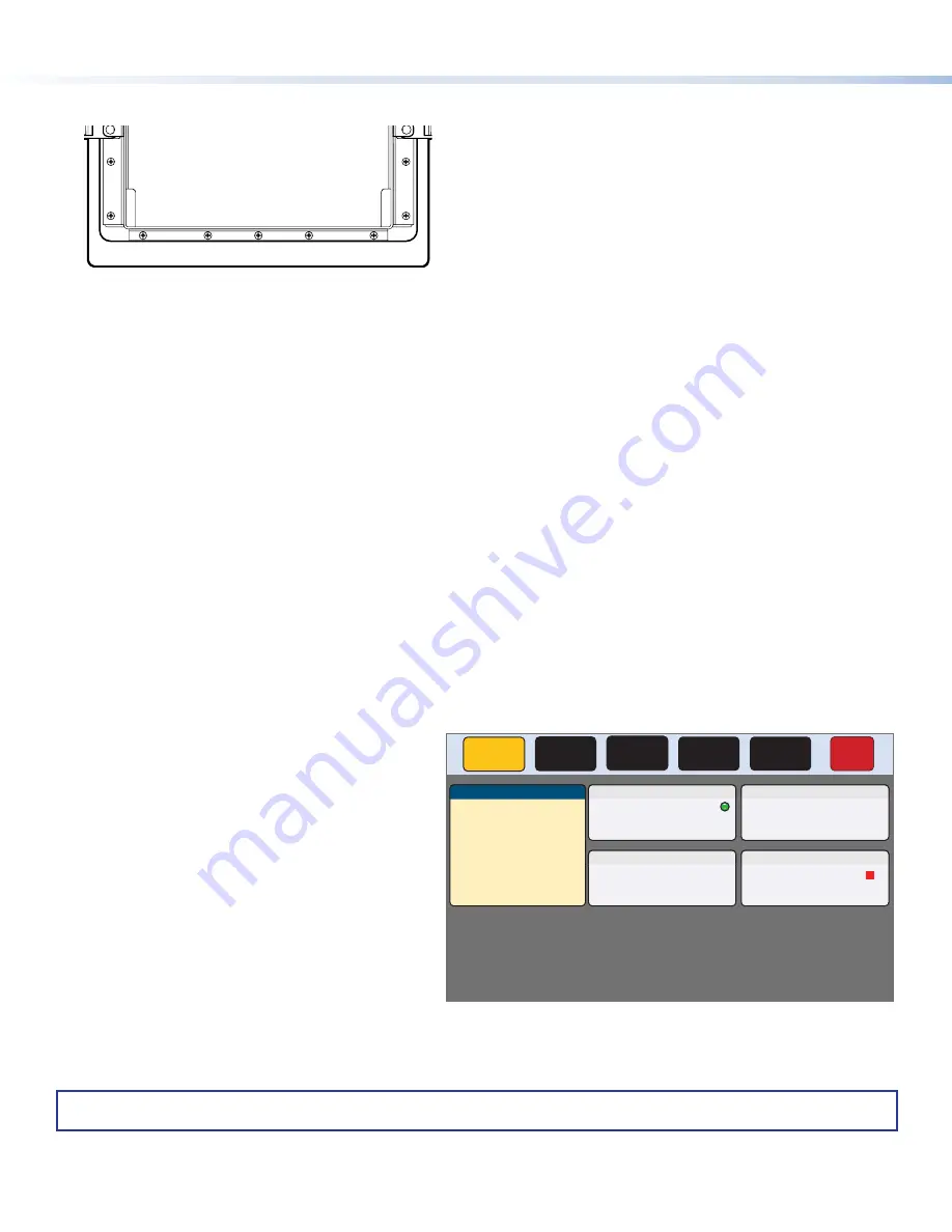
Setup Menu
Press the
Menu
button (figure 11,
E
) to open the
setup menu. Figure 12 shows the
Status
screen.
Select any of the five available screens (
Status
,
Network
,
Display
,
Audio
, and
Advanced
) by
pressing the appropriate button in the navigation bar
at the top of the screen (for more information, see the
TLP Pro 725C Series User Guide
).
Status
Display
Audio
Advanced
Exit
Network
Info
Model:
TLP Pro 725C
Part Number: 60-1564-02
Firmware
Version:
1.02.0001-b001
Network
IP Address:
DHCP:
Host Name:
Off
192.168.254.251
TLP-AB-CD-EF
Display
Resolution:
GUI Project:
Sleep Timer:
1024x600
N/A
5 Minutes
Audio
Master Volume:
Master Mute:
Off
99
Advanced
Controller IP:
N/A
Project Size:
N/A
Bootloader
Version:
1.03.0000
Figure 12.
Setup Menu: Status Screen
68-3319-50 Rev. A
09 18


