4
TLP Pro 725C Series • Setup Guide (Continued)
Step 3 — Run all Cables
Run all cables necessary to support the AC connector, the cables stored in the cubby, and all planned AAP connectors. Run the
cables below the table and through the hole that was cut in
Step 2 — Cut the Surface
on the previous page. Leave enough slack
in the cables to connect or route them before the cubby is installed in the table. Leave enough space under the TLP Pro 725C
enclosure for the external power supply and connection of AV cables and the network connection.
Step 4 — Install Cable Retractors (Optional)
If required, Extron cable retractors must be purchased separately. It is difficult to mount the Cable Cubby into the table after the
retractors have already been installed so Extron recommends installing the empty retractor bracket at this point. The bracket
should be secured using the lowest level of mounting holes inside the touchpanel enclosure.
The retractors should be added to the bracket after
Step 8 — Mounting the Enclosure
on page 6. For complete information
about retractors and how to install them, see the
TLP Pro 725C User Guide
and
Retractors User Guide
at
www.extron.com
.
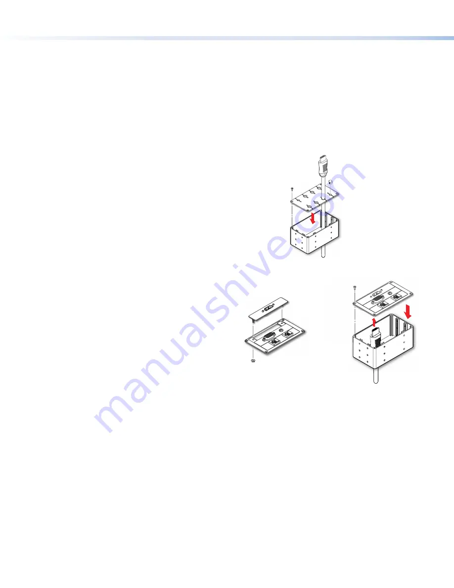
Step 5 — Assemble Pass-through Cable Module (Optional)
1.
Pass the cables through the connectivity module from the bottom (see
figure 5,
1
).
2.
Insert the cable into the grommet plate (
2
).
3.
Fill any unused holes with the provided plugs (
3
).
4.
Attach the grommet plate to the top of the connectivity module, using
four of the provided #4-40 thread forming screws (
4
).
To secure the pass-through cable module to the Touchpanel enclosure, see
Step 7 — Install Modules
on the next page.
3
2
1
4
Figure 5.
Installing pass-through cable module
Step 6 — Assemble AAP Module (Optional)
If required, AAPs must be purchased separately. Go to
www.extron.com
to see the full range of AAPs that are
available.
1.
Secure up to three single space AAPs in the AAP Frame,
using the #4-40 nut with captive washer provided with the
AAP (figure 6,
1
).
If required, fill any unused spaces with blank AAP plates.
2.
Insert cables through the bottom of the connectivity
module and connect them to the AAPs (
2
).
3.
Secure the AAP frame to the connectivity module, using
four of the provided #4-40 thread forming screws (
3
).
To secure the AAP module to the Touchpanel enclosure, see
Step 7 — Install Modules
on the next page.
3
2
#4-40 Nut with
Captive Washer
1
AAP
AAP Frame
Connectivity
Module
3
3
3
3
Figure 6.
Assemble the AAP Module


