4
TLC Pro 526M, 726M, and 1026M Series • Setup Guide (Continued)
Menu Button
on the previous page)— Activates the setup menu (see
Reset Button
— Pressing the Reset button allows the unit to be reset in any of four different modes and can also be used to
toggle between enabling and disabling the DHCP client (for an overview, see
Reset LED
— Provides feedback about the reset status when the user presses the Reset button (see
).
Mounting Slots
— The TLC Pro 726M and 1026M have four, one in each corner. The TLC Pro 526M has two, one in each
top corner. The hooks on the corners of the mounting plate (see
, on page 7) fit into these slots for wall
mounting.
Digital Input Monitoring Port
— This two-pole captive screw port (1 = signal and G = ground) monitors digital input with or
without a +5 VDC pull-up.
LAN/PoE Connector
— Connect the touchpanel to a PoE power injector (not provided) using a twisted pair cable,
terminated with an RJ-45 connector. Connect the power injector to the LAN through a nework switch.
ATTENTION:
•
The TLC Pro 526M, TLC Pro 726M and TLC Pro 1026M are Power over Ethernet (PoE 802.3af, class 3) compliant.
Do not power on the touchpanels until you have read the Attention in the “Rear Panel Features” section of the
TLC
Pro 526, 726, and 1026 Series User Guide
.
•
Le TLC Pro 526M, le TLC Pro 726M et le TLC Pro 1026M supportent l’alimentation via Ethernet (PoE 802.3af,
classe 3). Veuillez lire la partie « Attention » dans la section « Rear Panel Features » du TLC Pro 526, 726, and 1026
Series User Guide, avant de mettre sous tension les écrans tactiles.
Menu Button
Reset Button
Reset LED
Mounting Slots
Digital Input Monitoring Port
LAN/PoE Connector
NOTE:
These touchpanels are shipped without a power injector. The
power injector must be purchased separately.
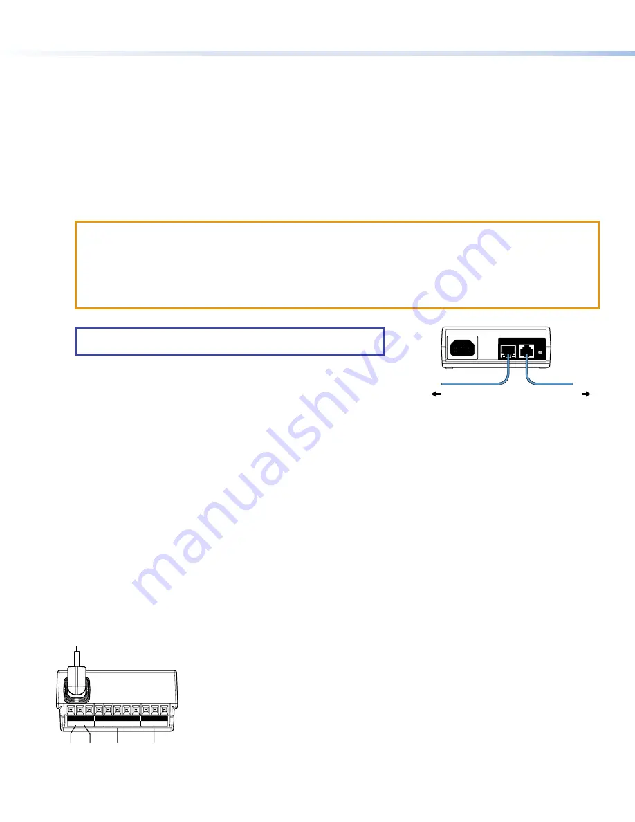
Extron recommends the Extron XTP PI 100 power injector (see figure 3).
Your power injector may look different.
figure 2
100-240V
~
50-60Hz
0.4A MAX
XTP
PWR
XTP PWR
To network switch
To touchpanel
Figure 3.
XTP PI 100 Power Injector
USB Port
— Compatible with USB 2.0.
Speaker
— Provides audible feedback for the user.
•
TLC Pro 526M — a single speaker
•
TLC Pro 726M — a single speaker
•
TLC Pro 1026M — two (dual mono) speakers
Mounting Plate Slot
— The tongue at the bottom of the plate (see
,
) fits into this slot, for wall mounting.
Mounting Screw
— Tightens against the tongue of the mounting plate to secure the touchpanel.
Rear Panel Status Lights
•
TLC Pro 526M — no lights
•
TLC Pro 726M — Six lights, three on each side of the panel
•
TLC Pro 1026M — Two lights, one on each side of the panel
These lights can provide system feedback by being configured to light red or green and to blink or stay continuously lit. For
information about configuring these LEDs, see the
Global Configurator Help File
.
The rear panel status lights can be toggled between enabled and disabled by using the
.
USB Adapter
— Provides additional control ports (see below).
USB Port
Speaker
Mounting Plate Slot
Mounting Screw
Rear Panel Status Lights
USB Adapter
USB Adapter Features
S G IN
1 2 C
Tx Rx
Rx
G Tx
IR/C IN
COM1
RELAYS
COM2
A
A
B
B C
C D
D
E
E
Figure 4.
USB Adapter Features
A
USB Connector — Insert connector into the USB Port (see
B
IR connector (shares ground with Contact Closure connector)
C
Contact Closure connector (shares ground wire with IR connector)
D
Communications ports (two, with shared ground wire)
E
Relay ports (two, with shared common wire)
For more information about these ports, see
Attaching the USB Adapter to the Touchpanel
1.
Connect the adapter to the USB port (see
2.
Use the provided zip tie to secure the adapter to the back of the touchpanel.


