background image


2

TLC Pro 526M, 726M, and 1026M Series • Setup Guide (Continued)

Set Up the Touchpanels for Network Communication


…

Connect the PC that you will use for setup and the TouchLink Pro control system 

to the same Ethernet subnetwork

.


…

Use the 

Setup Menu

 (see page 10) or Toolbelt to set the DHCP status and, if necessary, the IP address, subnet mask, 

gateway, and related settings for the control system.

Configure the TouchLink Pro Control System


…

Use GUI Designer to design, save, and build the graphical user interface layout for the touchpanel.


…

Use Global Configurator to configure the control system and the control ports.


…

Save and build the project and upload it to the TLC Pro control system.

The 

GUI Designer Help File

Global Configurator Help File

, and the 

Toolbelt Help File

 provide step-by-step instructions and more 

detailed information. The 

Global Configurator Help File

 includes an introduction to the software and sections on how to start a 

project and configuration. 

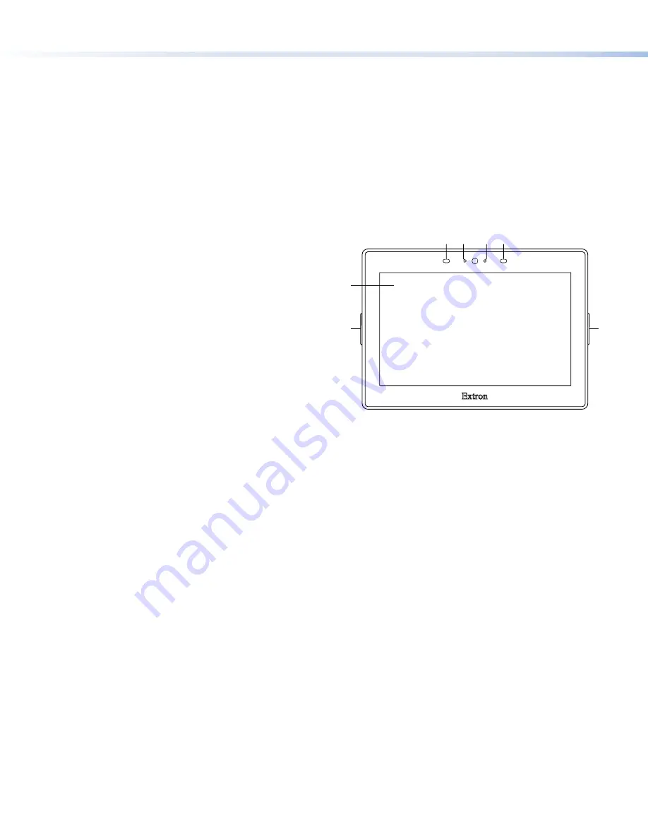
Front Panel Features

Figure 1 shows the front panel of the TLC Pro 726M. The front 
panels of all the touchpanels have the same features and are 
almost identical apart from the size.

A


Motion sensor

 — Detects motion between three to five 

feet from the touchpanel, and at least 15° from the center 
axis.

• 

When no motion has been detected for a user-defined 
period of time, the touchpanel enters sleep mode.

• 

When motion is detected by the sensor, the screen 
display is restored and active.

B


Communication LED

 — Shows the configuration and 

connection status of the touchpanel:

• 

Unlit during normal operation (the TouchLink Pro 
control system is correctly configured).

• 

Blinks red if the touchpanel has been configured but is 
not communicating correctly with the TLC Pro control 
system.

• 

Lit solidly red if the touchpanel has not been configured.

• 

The indicator can be toggled between enabled and disabled, using the 

Setup Menu

 (see page 10). 

C


Light sensor

 — Monitors ambient light level and adjusts screen brightness.

D


Capacitive touchscreen

 — 

• 

The TLC Pro 526M series has a 5-inch screen with a 800x480 resolution

• 

The TLC Pro 726M series has a 7-inch screen with a 1024x600 resolution

• 

The TLC Pro 1026M series has a 10.1-inch screen with a 1280x800 resolution

E


Status lights

 — Two LED light bars, one on either side of the screen, which can be programmed to provide system feedback, 

by lighting red or green and by blinking or staying continuously lit. For information about configuring these LEDs, see the 

Global 

Configurator Help File

.

A

A B

B

C

C A

A

D

D

E

E

E

E

Figure 1. 

 TLC Pro 726M Front Panel

Содержание TLC Pro 526M Series

Страница 1: ...rk information from your network administrator DHCP status on or off If DHCP is off you will also require IP address Subnet mask Gateway User name this can be either admin or user Password the factory configured passwords are the serial number of the touchpanel for either admin or user NOTE The factory configured passwords for all accounts on this device have been set to the device serial number I...

Страница 2: ... motion between three to five feet from the touchpanel and at least 15 from the center axis When no motion has been detected for a user defined period of time the touchpanel enters sleep mode When motion is detected by the sensor the screen display is restored and active B Communication LED Shows the configuration and connection status of the touchpanel Unlit during normal operation the TouchLink ...

Страница 3: ... E E F F G G D D D D K K D D D D I I J J TLC Pro 1026M L L e TLC Pro 526M with USB Adapter in Place A Menu Button on next page B Reset Button on next page C Reset LED on next page D Mounting Slots on next page E Digital Input Monitoring Port on next page F LAN PoE Connector on next page G USB Port on next page H Speaker on next page I Mounting Plate Slot on next page J Mounting Screw on next page ...

Страница 4: ...without a power injector The power injector must be purchased separately Extron recommends the Extron XTP PI 100 power injector see figure 3 Your power injector may look different 100 240V 50 60Hz 0 4A MAX XTP PWR XTP PWR To network switch To touchpanel Figure 3 XTP PI 100 Power Injector G USB Port Compatible with USB 2 0 H Speaker Provides audible feedback for the user TLC Pro 526M a single speak...

Страница 5: ...d of the emitter over or next to the IR signal pickup window of the device being controlled Connect two wires to the IR port as shown in figure 6 If both the IR port and contact closure port are used the ground pin must be shared by both devices NOTE Each emitter must be within 100 feet 30 4 meters of the TLC Pro control system for best IR control results S G IN IR C IN To the IR Receiver of a Pro...

Страница 6: ...y or odd parity default no parity This port supports flow control The default is no flow control NOTE The maximum distance from the touchpanel to the device being controlled is usually 200 feet 61 m but this can vary depending on factors such as cable gauge baud rates environment and output levels from the touchpanel and the device being controlled To wire the ports see figure 11 If single port is...

Страница 7: ... be wall mounted either using a UL listed junction box an external wall box or directly into drywall or furniture Suitable mounting accessories can be found at www extron com ATTENTION Do not install touchpanels in a fire resistant rated wall or partition assembly Ne pas installer les écrans tactiles sur un mur protégé par un dispositif coupe feu ou dans une cloison All structural steps and electr...

Страница 8: ...has two hooks one in each top corner The TLC Pro 726M and TLC Pro 1026M mounting plate has four hooks 3 one in each corner see figure 14 below Position the touch panel so that the mounting slots see figure 2 D on page 3 in the rear of the touchpanel align with these hooks 6 Move the touchpanel inward and downward so that touchpanel sits securely on the hooks and the tongue at the bottom of the mou...

Страница 9: ...e version you must upload that version again Project Recovery This mode is activated using Global Configurator Plus and Professional See the Global Configurator Help File for more information Run Stop Program Hold down the Reset button for about 3 seconds until the Power LED blinks once Release and press the Reset button momentarily for 1 second within 1 second Nothing happens if the momentary pre...

Страница 10: ...2 A on page 3 Figure 15 shows the TLC Pro 526M menu The setup menus for the other touchpanels are very similar There are five different screens Status shown in figure 15 Network Display Audio and Advanced The screens can be selected by pressing the appropriate button in the navigation bar at the top of the screen for more information see the TLC Pro 526M 726M and 1026M User Guide Status Display Au...

Отзывы: