background image


6

TLC Pro 526M, 726M, and 1026M Series • Setup Guide (Continued)

Contact closure

The contact closure port is used to monitor switches, sensors, or similar devices and trigger events in response to changes to the 
monitored device. Insert the wires from the monitored device into the contact closure port. 
A 1k ohm pull-up resistor in a TTL (5 VDC) circuit senses the contact closure.

• 

When the external switch closes (shorts to ground, logic low) the port is on.

• 

When the external switch opens (logic high) the port is off.

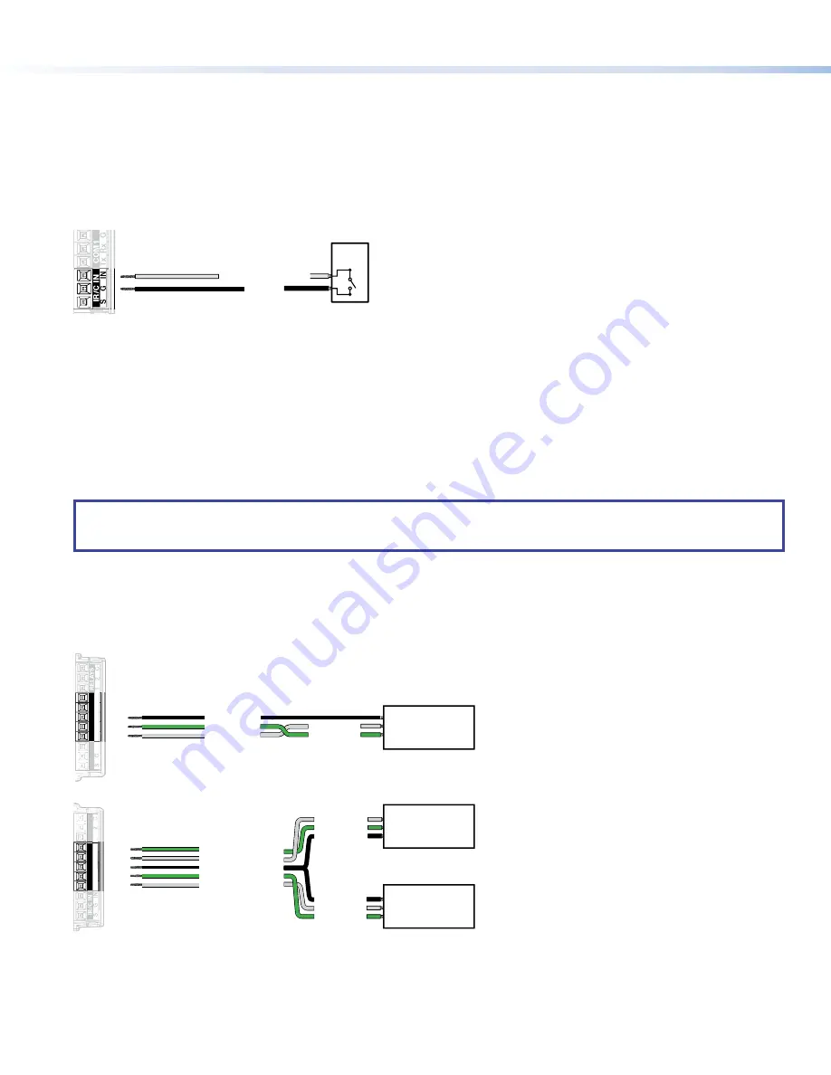
Connect two wires to the contact closure port, as shown in figure 10. If both the IR port and contact closure port are used, the 
ground pin must be shared by both devices.

SG

IN

IR/C IN

Ground

Contact Closure Input

Switch,

Sensor

Figure 10. 

 Contact Closure Port

COM ports

The TLC Pro Control System has two COM ports, which support software flow control. They share a common ground pin. COM 
ports control and receive status messages from connected devices, using the following RS-232 protocols:

• 

300 to 115200 baud (default = 9600 baud)

• 

7 or 8 data bits (default = 8)

• 

1 or 2 stop bits (default = 1)

• 

No parity, even parity, or odd parity (default = no parity)

• 

This port supports flow control. The default is no flow control.

NOTE:

  The maximum distance from the touchpanel to the device being controlled is usually 200 feet (61 m), but this can vary, 

depending on factors such as cable gauge, baud rates, environment, and output levels from the touchpanel and the device 
being controlled.

To wire the ports, see figure 11. If single port is used, it can be wired using either COM 1 or COM 2. (Figure 11 shows COM 1.)
For bidirectional serial communication, the transmit, ground, and receive pins must be wired at both the adapter and the device 
being controlled. For information about wiring the device being controlled, see the user guide for that device.
If you use cable that has drain wire, the drain wire must be tied to ground at both ends. For best results, insulate the common or 
drain wires using heat shrink.

Receive (Rx)

Transmit (Tx)

Transmit

COM 1 Rx

Receive

COM 1 Tx

G

Ground

1

Tx

Rx

Rx

G

Tx

COM1

RELA

YS

COM2

1

RELA

Y

S

IN

Tx

Rx

Rx

G

Tx

IR/C IN

COM1

COM2

IN

IR/C 

IN

Transmit

COM 2 Rx

Receive

COM 2 Tx

Ground

Receive (Rx)

Transmit (Tx)

Ground

Device

controlled by

RS-232

Receive (Rx)

Transmit (Tx)

Transmit

Rx

Receive

Tx

G

Ground

Device 2

controlled by

RS-232

Device 1

controlled by

RS-232

Wiring a single COM port

Wiring both COM ports

Figure 11. 

 COM Ports

Содержание TLC Pro 526M Series

Страница 1: ...rk information from your network administrator DHCP status on or off If DHCP is off you will also require IP address Subnet mask Gateway User name this can be either admin or user Password the factory configured passwords are the serial number of the touchpanel for either admin or user NOTE The factory configured passwords for all accounts on this device have been set to the device serial number I...

Страница 2: ... motion between three to five feet from the touchpanel and at least 15 from the center axis When no motion has been detected for a user defined period of time the touchpanel enters sleep mode When motion is detected by the sensor the screen display is restored and active B Communication LED Shows the configuration and connection status of the touchpanel Unlit during normal operation the TouchLink ...

Страница 3: ... E E F F G G D D D D K K D D D D I I J J TLC Pro 1026M L L e TLC Pro 526M with USB Adapter in Place A Menu Button on next page B Reset Button on next page C Reset LED on next page D Mounting Slots on next page E Digital Input Monitoring Port on next page F LAN PoE Connector on next page G USB Port on next page H Speaker on next page I Mounting Plate Slot on next page J Mounting Screw on next page ...

Страница 4: ...without a power injector The power injector must be purchased separately Extron recommends the Extron XTP PI 100 power injector see figure 3 Your power injector may look different 100 240V 50 60Hz 0 4A MAX XTP PWR XTP PWR To network switch To touchpanel Figure 3 XTP PI 100 Power Injector G USB Port Compatible with USB 2 0 H Speaker Provides audible feedback for the user TLC Pro 526M a single speak...

Страница 5: ...d of the emitter over or next to the IR signal pickup window of the device being controlled Connect two wires to the IR port as shown in figure 6 If both the IR port and contact closure port are used the ground pin must be shared by both devices NOTE Each emitter must be within 100 feet 30 4 meters of the TLC Pro control system for best IR control results S G IN IR C IN To the IR Receiver of a Pro...

Страница 6: ...y or odd parity default no parity This port supports flow control The default is no flow control NOTE The maximum distance from the touchpanel to the device being controlled is usually 200 feet 61 m but this can vary depending on factors such as cable gauge baud rates environment and output levels from the touchpanel and the device being controlled To wire the ports see figure 11 If single port is...

Страница 7: ... be wall mounted either using a UL listed junction box an external wall box or directly into drywall or furniture Suitable mounting accessories can be found at www extron com ATTENTION Do not install touchpanels in a fire resistant rated wall or partition assembly Ne pas installer les écrans tactiles sur un mur protégé par un dispositif coupe feu ou dans une cloison All structural steps and electr...

Страница 8: ...has two hooks one in each top corner The TLC Pro 726M and TLC Pro 1026M mounting plate has four hooks 3 one in each corner see figure 14 below Position the touch panel so that the mounting slots see figure 2 D on page 3 in the rear of the touchpanel align with these hooks 6 Move the touchpanel inward and downward so that touchpanel sits securely on the hooks and the tongue at the bottom of the mou...

Страница 9: ...e version you must upload that version again Project Recovery This mode is activated using Global Configurator Plus and Professional See the Global Configurator Help File for more information Run Stop Program Hold down the Reset button for about 3 seconds until the Power LED blinks once Release and press the Reset button momentarily for 1 second within 1 second Nothing happens if the momentary pre...

Страница 10: ...2 A on page 3 Figure 15 shows the TLC Pro 526M menu The setup menus for the other touchpanels are very similar There are five different screens Status shown in figure 15 Network Display Audio and Advanced The screens can be selected by pressing the appropriate button in the navigation bar at the top of the screen for more information see the TLC Pro 526M 726M and 1026M User Guide Status Display Au...

Отзывы: