background image


4

TLC Pro 526M, 726M, and 1026M Series • Setup Guide (Continued)

A


Menu Button

 (see 

figure 2

 on the previous page)— Activates the setup menu (see 

Setup Menu

 on page 10).

B


Reset Button

 — Pressing the Reset button allows the unit to be reset in any of four different modes and can also be used to 

toggle between enabling and disabling the DHCP client (for an overview, see 

Reset Modes: a Brief Summary

 on page 9).

C


Reset LED

 — Provides feedback about the reset status when the user presses the Reset button (see 

Reset Modes: a Brief 

Summary

).

D


Mounting Slots

 — The TLC Pro 726M and 1026M have four, one in each corner. The TLC Pro 526M has two, one in each 

top corner. The hooks on the corners of the mounting plate (see 

figure 13

3

, on page 7) fit into these slots for wall 

mounting.

E


Digital Input Monitoring Port

 — This two-pole captive screw port (1 = signal and G = ground) monitors digital input with or 

without a +5 VDC pull-up. 

F


LAN/PoE Connector

 — Connect the touchpanel to a PoE power injector (not provided) using a twisted pair cable, 

terminated with an RJ-45 connector. Connect the power injector to the LAN through a nework switch.

ATTENTION:

• 

The TLC Pro 526M, TLC Pro 726M and TLC Pro 1026M are Power over Ethernet (PoE 802.3af, class 3) compliant. 
Do not power on the touchpanels until you have read the Attention in the “Rear Panel Features” section of the 

TLC 

Pro 526, 726, and 1026 Series User Guide

.

• 

Le TLC Pro 526M, le TLC Pro 726M et le TLC Pro 1026M supportent l’alimentation via Ethernet (PoE 802.3af, 
classe 3). Veuillez lire la partie « Attention » dans la section « Rear Panel Features » du TLC Pro 526, 726, and 1026 
Series User Guide, avant de mettre sous tension les écrans tactiles.

Menu Button
Reset Button

Reset LED

Mounting Slots

Digital Input Monitoring Port

LAN/PoE Connector

NOTE:

  These touchpanels are shipped without a power injector. The 

power injector must be purchased separately.

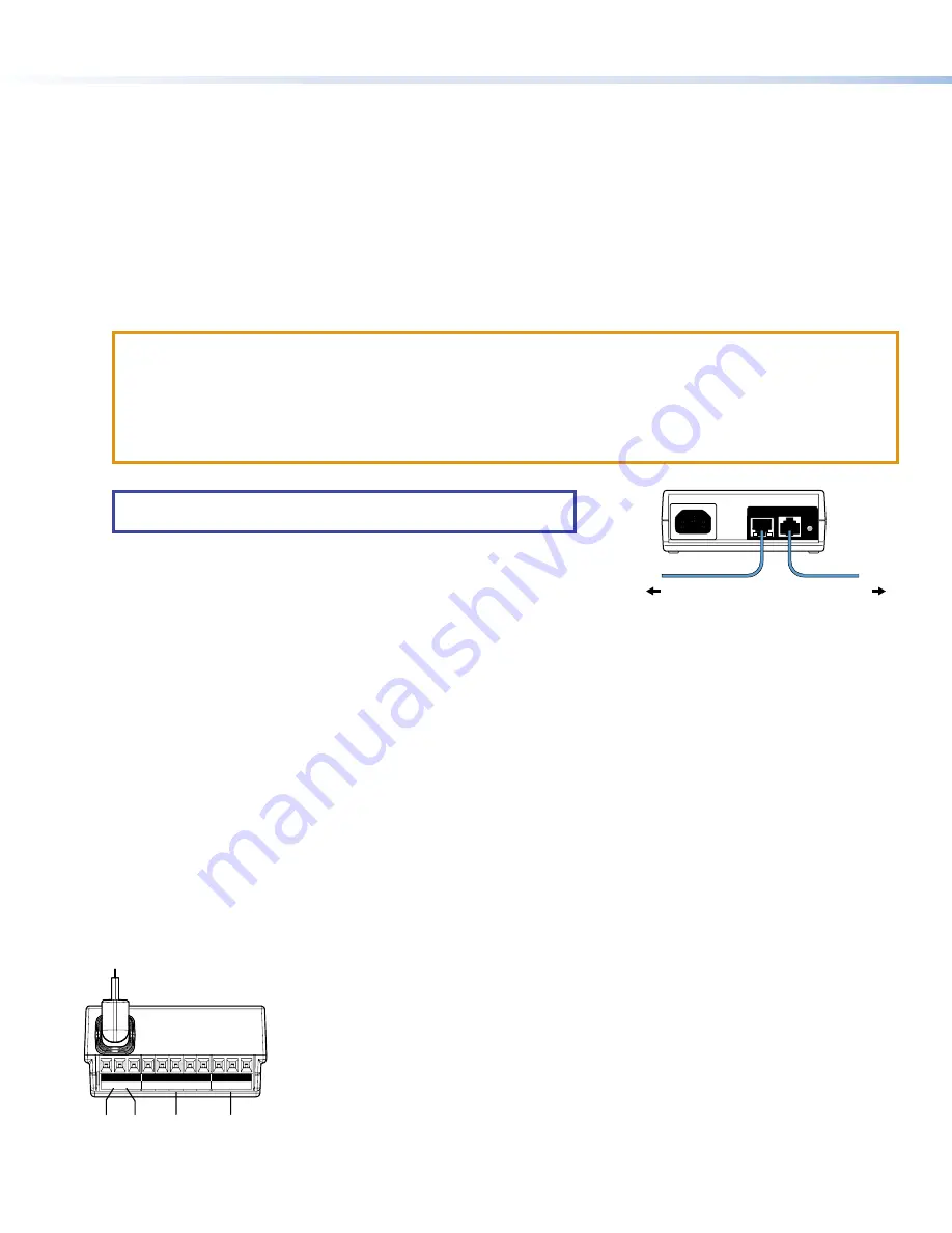
Extron recommends the Extron XTP PI 100 power injector (see figure 3). 
Your power injector may look different.

figure 2

100-240V 

~

 50-60Hz

0.4A MAX

XTP

PWR

XTP PWR

To network switch

To touchpanel

Figure 3. 

XTP PI 100 Power Injector

G


USB Port

 — Compatible with USB 2.0. 

H


Speaker 

— Provides audible feedback for the user.

• 

TLC Pro 526M — a single speaker

• 

TLC Pro 726M — a single speaker

• 

TLC Pro 1026M — two (dual mono) speakers

I


Mounting Plate Slot

 — The tongue at the bottom of the plate (see 

figure 13

4

) fits into this slot, for wall mounting.

J


Mounting Screw

 — Tightens against the tongue of the mounting plate to secure the touchpanel.

K


Rear Panel Status Lights

• 

TLC Pro 526M — no lights

• 

TLC Pro 726M — Six lights, three on each side of the panel

• 

TLC Pro 1026M — Two lights, one on each side of the panel

These lights can provide system feedback by being configured to light red or green and to blink or stay continuously lit. For 
information about configuring these LEDs, see the 

Global Configurator Help File

.

The rear panel status lights can be toggled between enabled and disabled by using the 

Setup Menu

.

L


USB Adapter

 — Provides additional control ports (see below). 

USB Port
Speaker

Mounting Plate Slot

Mounting Screw

Rear Panel Status Lights

USB Adapter

USB Adapter Features

S G IN

1 2 C

Tx Rx

Rx

G Tx

IR/C IN

COM1

RELAYS

COM2

A

A

B

B C

C D

D

E

E

Figure 4. 

USB Adapter Features

A

USB Connector — Insert connector into the USB Port (see 

figure 2

 on page 4, 

G

)

B

IR connector (shares ground with Contact Closure connector)

C

Contact Closure connector (shares ground wire with IR connector)

D

Communications ports (two, with shared ground wire)

E

Relay ports (two, with shared common wire)

For more information about these ports, see 

Control Ports — USB Adapter

 on page 5)

Attaching the USB Adapter to the Touchpanel

1. 

Connect the adapter to the USB port (see 

figure 2

G

 on page 3).

2. 

Use the provided zip tie to secure the adapter to the back of the touchpanel.

Содержание TLC Pro 526M Series

Страница 1: ...rk information from your network administrator DHCP status on or off If DHCP is off you will also require IP address Subnet mask Gateway User name this can be either admin or user Password the factory configured passwords are the serial number of the touchpanel for either admin or user NOTE The factory configured passwords for all accounts on this device have been set to the device serial number I...

Страница 2: ... motion between three to five feet from the touchpanel and at least 15 from the center axis When no motion has been detected for a user defined period of time the touchpanel enters sleep mode When motion is detected by the sensor the screen display is restored and active B Communication LED Shows the configuration and connection status of the touchpanel Unlit during normal operation the TouchLink ...

Страница 3: ... E E F F G G D D D D K K D D D D I I J J TLC Pro 1026M L L e TLC Pro 526M with USB Adapter in Place A Menu Button on next page B Reset Button on next page C Reset LED on next page D Mounting Slots on next page E Digital Input Monitoring Port on next page F LAN PoE Connector on next page G USB Port on next page H Speaker on next page I Mounting Plate Slot on next page J Mounting Screw on next page ...

Страница 4: ...without a power injector The power injector must be purchased separately Extron recommends the Extron XTP PI 100 power injector see figure 3 Your power injector may look different 100 240V 50 60Hz 0 4A MAX XTP PWR XTP PWR To network switch To touchpanel Figure 3 XTP PI 100 Power Injector G USB Port Compatible with USB 2 0 H Speaker Provides audible feedback for the user TLC Pro 526M a single speak...

Страница 5: ...d of the emitter over or next to the IR signal pickup window of the device being controlled Connect two wires to the IR port as shown in figure 6 If both the IR port and contact closure port are used the ground pin must be shared by both devices NOTE Each emitter must be within 100 feet 30 4 meters of the TLC Pro control system for best IR control results S G IN IR C IN To the IR Receiver of a Pro...

Страница 6: ...y or odd parity default no parity This port supports flow control The default is no flow control NOTE The maximum distance from the touchpanel to the device being controlled is usually 200 feet 61 m but this can vary depending on factors such as cable gauge baud rates environment and output levels from the touchpanel and the device being controlled To wire the ports see figure 11 If single port is...

Страница 7: ... be wall mounted either using a UL listed junction box an external wall box or directly into drywall or furniture Suitable mounting accessories can be found at www extron com ATTENTION Do not install touchpanels in a fire resistant rated wall or partition assembly Ne pas installer les écrans tactiles sur un mur protégé par un dispositif coupe feu ou dans une cloison All structural steps and electr...

Страница 8: ...has two hooks one in each top corner The TLC Pro 726M and TLC Pro 1026M mounting plate has four hooks 3 one in each corner see figure 14 below Position the touch panel so that the mounting slots see figure 2 D on page 3 in the rear of the touchpanel align with these hooks 6 Move the touchpanel inward and downward so that touchpanel sits securely on the hooks and the tongue at the bottom of the mou...

Страница 9: ...e version you must upload that version again Project Recovery This mode is activated using Global Configurator Plus and Professional See the Global Configurator Help File for more information Run Stop Program Hold down the Reset button for about 3 seconds until the Power LED blinks once Release and press the Reset button momentarily for 1 second within 1 second Nothing happens if the momentary pre...

Страница 10: ...2 A on page 3 Figure 15 shows the TLC Pro 526M menu The setup menus for the other touchpanels are very similar There are five different screens Status shown in figure 15 Network Display Audio and Advanced The screens can be selected by pressing the appropriate button in the navigation bar at the top of the screen for more information see the TLC Pro 526M 726M and 1026M User Guide Status Display Au...

Отзывы: