background image


7

Product Category

Relays

There are two relay ports, which share a common ground. These ports may be used to control any equipment as long as the 
contact specifications of a total of 24 V at 1 A are not exceeded for each port. These relays are normally open by default.
When activated, the open contacts close. They can be set up to operate in one of two ways:

• 

Latching (brief or indefinite period contact) (press to close, press to open), or

• 

Pulsed (timed cycle) (press to close, timeout to open, with automatic repeat).

In pulse mode the default timeout period (hold time) is 0.5 second (500 ms). This time can be changed with Global Configurator.

NOTE:

  The pulse function is absolute: it always sets the relay state to closed, times out (briefly), then opens the contact. It 

overrides the previously selected setting (on state, off state, or toggle).

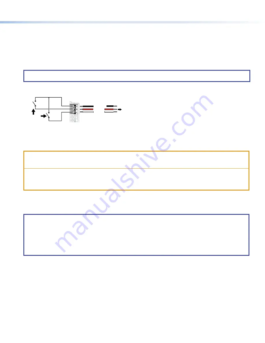
To use a single relay port connect Pin 3 (C) and either Pin 1 (Relay 1) or Pin 2 (Relay 2) to the device being controlled. To use both 
relay ports, connect the pins as shown in figure 12. Pin 3 (C) must be connected to both devices being controlled.

Normally

Open (2)

Common

Normally

Open (1)

Common

All relays are 

normally open.

To Room 

Control 

Equipment

Common

Relay 2

Relay 1

12

C

RELA

YS

Figure 12. 

 Relay Ports

Mounting

All these touchpanels can be wall-mounted, either using a UL-listed junction box, an external wall box, or directly into drywall or 
furniture. Suitable mounting accessories can be found at 

www.extron.com

.

ATTENTION:

• 

Do not install touchpanels in a fire resistant rated wall or partition assembly.

• 

Ne pas installer les écrans tactiles sur un mur protégé par un dispositif coupe-feu ou dans une cloison.

• 

All structural steps and electrical installation must be performed by qualified personnel in accordance with local and 
national building codes and electrical codes.

• 

Toute étape structurelle et installation électrique doit être effectuée par un personnel qualifié, conformément aux 
codes de sécurité de bâtiments et de produits électriques en vigueur à l’échelle régionale et nationale.

With a Wall Box or Junction Box

Some local building codes require the touchpanel to be mounted in a junction box. Junction boxes or wall boxes must be 
purchased separately. 

NOTES:

• 

The TLC Pro 526M mounts to a 1-gang junction box. The US 1-gang junction box should be installed so that the long 
side is horizontal. EU or MK 1-gang junction boxes should be installed in the standard orientation.

• 

The TLC Pro 726M and 1026M touchpanels mount to a 2-gang junction box.

• 

Extron provides four 3/4" #6-32 Philips pan head screws for mounting to US junction boxes.

• 

Extron provides two 16 mm M 3.5 Philips pan head screws for mounting to MK junction boxes.

• 

EU junction boxes are usually provided with their own screws.

figure 12

Содержание TLC Pro 526M Series

Страница 1: ...rk information from your network administrator DHCP status on or off If DHCP is off you will also require IP address Subnet mask Gateway User name this can be either admin or user Password the factory configured passwords are the serial number of the touchpanel for either admin or user NOTE The factory configured passwords for all accounts on this device have been set to the device serial number I...

Страница 2: ... motion between three to five feet from the touchpanel and at least 15 from the center axis When no motion has been detected for a user defined period of time the touchpanel enters sleep mode When motion is detected by the sensor the screen display is restored and active B Communication LED Shows the configuration and connection status of the touchpanel Unlit during normal operation the TouchLink ...

Страница 3: ... E E F F G G D D D D K K D D D D I I J J TLC Pro 1026M L L e TLC Pro 526M with USB Adapter in Place A Menu Button on next page B Reset Button on next page C Reset LED on next page D Mounting Slots on next page E Digital Input Monitoring Port on next page F LAN PoE Connector on next page G USB Port on next page H Speaker on next page I Mounting Plate Slot on next page J Mounting Screw on next page ...

Страница 4: ...without a power injector The power injector must be purchased separately Extron recommends the Extron XTP PI 100 power injector see figure 3 Your power injector may look different 100 240V 50 60Hz 0 4A MAX XTP PWR XTP PWR To network switch To touchpanel Figure 3 XTP PI 100 Power Injector G USB Port Compatible with USB 2 0 H Speaker Provides audible feedback for the user TLC Pro 526M a single speak...

Страница 5: ...d of the emitter over or next to the IR signal pickup window of the device being controlled Connect two wires to the IR port as shown in figure 6 If both the IR port and contact closure port are used the ground pin must be shared by both devices NOTE Each emitter must be within 100 feet 30 4 meters of the TLC Pro control system for best IR control results S G IN IR C IN To the IR Receiver of a Pro...

Страница 6: ...y or odd parity default no parity This port supports flow control The default is no flow control NOTE The maximum distance from the touchpanel to the device being controlled is usually 200 feet 61 m but this can vary depending on factors such as cable gauge baud rates environment and output levels from the touchpanel and the device being controlled To wire the ports see figure 11 If single port is...

Страница 7: ... be wall mounted either using a UL listed junction box an external wall box or directly into drywall or furniture Suitable mounting accessories can be found at www extron com ATTENTION Do not install touchpanels in a fire resistant rated wall or partition assembly Ne pas installer les écrans tactiles sur un mur protégé par un dispositif coupe feu ou dans une cloison All structural steps and electr...

Страница 8: ...has two hooks one in each top corner The TLC Pro 726M and TLC Pro 1026M mounting plate has four hooks 3 one in each corner see figure 14 below Position the touch panel so that the mounting slots see figure 2 D on page 3 in the rear of the touchpanel align with these hooks 6 Move the touchpanel inward and downward so that touchpanel sits securely on the hooks and the tongue at the bottom of the mou...

Страница 9: ...e version you must upload that version again Project Recovery This mode is activated using Global Configurator Plus and Professional See the Global Configurator Help File for more information Run Stop Program Hold down the Reset button for about 3 seconds until the Power LED blinks once Release and press the Reset button momentarily for 1 second within 1 second Nothing happens if the momentary pre...

Страница 10: ...2 A on page 3 Figure 15 shows the TLC Pro 526M menu The setup menus for the other touchpanels are very similar There are five different screens Status shown in figure 15 Network Display Audio and Advanced The screens can be selected by pressing the appropriate button in the navigation bar at the top of the screen for more information see the TLC Pro 526M 726M and 1026M User Guide Status Display Au...

Отзывы: