background image

IPL Pro Series • Hardware Features and Installation

21

Resetting the Unit

There are four reset modes that are available by pressing the  

Reset

 button on the front panel. The 

Reset

 button is recessed, so use 

a pointed stylus, ballpoint pen, or Extron Tweeker to access it. See the 
reset modes table below and on the next page for a summary of the 
modes.

ATTENTION:


• 

Review the reset modes carefully. Using the wrong reset mode 
may result in unintended loss of flash memory programming, 
port reassignment, or a unit reboot.

• 

Analysez minutieusement les différents modes de 
réinitialisation. Appliquer le mauvais mode de réinitialisation 
peut causer une perte inattendue de la programmation 
de la mémoire flash, une reconfiguration des ports ou une 
réinitialisation de l’unité.

NOTE:

  If you hold down the 

Reset

 button continuously, the LED blinks every 

3 seconds, and the unit enters a different mode, from the Reset all IP Settings mode 
through the Reset to Factory Defaults mode. For Reset to Factory Defaults mode 
the LED blinks three times, the third blink indicating the last mode. The modes are 
separate functions, not a continuation from one mode to the next.

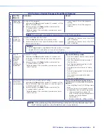
IPL Pro Series Control Processor Reset Mode Summary

Mode

Use This 
Mode to...

Activation

Result

Use Factory Firmwar

e

Temporarily 

boot up the 

unit with 

factory-

installed 

firmware for a 

single power 

cycle in the 

event that 

a firmware 

update has 

failed or if 

incompatibility 

issues arise 

with user-

loaded 

firmware

To start the Use Factory Firmware reset mode and replace 

firmware:

1. 

On the control processor, hold down the recessed 

Reset


button while applying power to the unit. Keep holding the 

button down until the 

Power

 LED blinks twice, then release 

the button. The control processor enters factory firmware 

mode, and the LED blinks quickly.

2. 

Upload new firmware to the unit as desired (see 

Updating 

the Firmware

 on page 34 for details).

NOTE:


Do not

 continue to operate the IPL Pro control 

processor using the factory firmware version. If you want to 
use the factory default firmware version, you must upload 
that version again. See the 

Global Configurator Help File


for firmware upload instructions.

The control processor reverts to the 

factory default firmware.

 Event scripting 

does not start if the unit is powered on in 

this mode. All user files and settings such 

as drivers, adjustments, and IP settings are 

maintained.

NOTE:

 To return the unit to the firmware 

version that was running prior to the 
reset, cycle power to the unit.

R

Power

LED

Reset 

Button

Rev. E, 7/2018: 

Changed “Hold: to 
“Keep holding”...

Содержание IPL Pro CR88

Страница 1: ...IPL Pro Series IP Link Pro Control Processors 68 2437 01 Rev E 09 18 User Guide IP Link Pro Products ...

Страница 2: ...nce importantes qui se trouvent dans la documentation fournie avec le matériel Pour en savoir plus sur les règles de sécurité la conformité à la réglementation la compatibilité EMI EMF l accessibilité et autres sujets connexes lisez les informations de sécurité et de conformité Extron réf 68 290 01 sur le site Extron www extron com Istruzioni di sicurezza Italiano AVVERTENZA Il simbolo se usato su...

Страница 3: ...tems Inc or Extron Electronics see the current list of trademarks on the Terms of Use page at www extron com Registered Trademarks Extron Cable Cubby ControlScript CrossPoint DTP eBUS EDID Manager EDID Minder Flat Field FlexOS Global Configurator Global Scripter GlobalViewer Hideaway HyperLane IP Intercom IP Link Key Minder LinkLicense LockIt MediaLink MediaPort NetPA PlenumVault PoleVault PowerCa...

Страница 4: ... interference must be corrected at the expense of the user NOTE For more information on safety guidelines regulatory compliances EMI EMF compatibility accessibility and related topics see the Extron Safety and Regulatory Compliance Guide on the Extron website Battery Notice This product contains a battery Do not open the unit to replace the battery If the battery needs replacing return the entire ...

Страница 5: ...responses mentioned in this guide the character 0 is used for the number zero and O is the capital letter o Computer responses and directory paths that do not have variables are written in the font shown here Reply from 208 132 180 48 bytes 32 times 2ms TTL 32 C Program Files Extron Variables are written in slanted form as shown here ping xxx xxx xxx xxx t SOH R Data STX Command ETB ETX Selectable...

Страница 6: ......

Страница 7: ...d Downloading the Firmware 34 Installing Firmware 34 Introduction 1 Before You Begin 1 What This Guide Covers 1 Conventions Used in This Guide 1 Important Information You Need Before Installation 1 About the IPL Pro Series 2 Features 3 Application Diagrams 4 Device Control 5 About Global Configurator with GC Professional and GC Plus Modes 5 About Global Scripter 5 PC System Requirements 6 Hardware...

Страница 8: ...IPL Pro Series Contents vi ...

Страница 9: ...d in the Global Configurator Help File the Global Scripter Help File and help files for related programs The software help files describe how to use each program to download drivers add AV devices to a configuration configure basic functions and set up schedules macros e mail alerts touchpanel button configurations and the like Conventions Used in This Guide Throughout this guide the IPL Pro Serie...

Страница 10: ... Ethernet network The touchpanels provide a convenient interface for controlling the IPL which in turn controls the other system components NOTE GUI Designer is used to design the user interface layout of any Extron TouchLink Pro touchpanel that is used with the IPL Use the Extron Toolbelt software to discover and manage the IPL Pro control processor and other Extron control products Configure the...

Страница 11: ...tandard Ethernet communication protocols including DHCP DNS HTTP HTTPS ICMP NTP SFTP SMTP SNMP SSH TCP IP and UDP IP Embedded web pages The IPL embedded web pages include online diagnostics and monitoring of basic features Remote equipment management The IP Link Pro connection allows you to remotely manage monitor and control several Ethernet enabled products such as projectors cameras video confe...

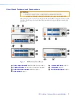
Страница 12: ...ROUNDED EARTHED DO NOT OBSTRUCT VENTILATION GRILLES DO NOT EXPOSE THIS EQUIPMENT TO RAIN OR MOISTURE ATTENTION OBSERVE PRECAUTIONS FOR HANDLING ELECTROSTATIC SENSITIVE DEVICES OUT HDCP COMPLIANT OUT HDCP COMPLIANT IN HDCP COMPLIANT IN HDCP COMPLIANT IN IN IN POWER 12V X XA MAX G Tx Rx RTS CTS COM 1 G Tx Rx RTS CTS COM 3 G Tx Rx RTS CTS COM 2 G Tx Rx RTS CTS COM 4 G Tx Rx RTS CTS COM 6 G Tx Rx RTS ...

Страница 13: ...About Global Configurator with GC Professional and GC Plus Modes Global Configurator Loads device drivers for monitoring the status of and controlling devices within the AV system Uploads GUI Designer interface layouts to touchpanels and third party touch interfaces Creates the configuration containing all the settings for the control processor and the products with which it interacts in the AV sy...

Страница 14: ...wnload index aspx on the Extron website and navigate to the web page for the specific software package such as Global Configurator and GUI Designer Minimum system requirements are listed in the description section In some cases minimum device firmware version requirements are also listed there If system requirements are not listed on the software package web page contact an Extron support represen...

Страница 15: ...the installation and configuration process Setup Checklist How to Proceed With Installation Get Ready Familiarize yourself with the features of the control processor see Front Panel Features on page 11 and Rear Panel Features and Connections on page 13 and of any TouchLink Pro touchpanels that are part of the system Download and install the latest version of the following Toolbelt software for dis...

Страница 16: ... setup the control processor and touchpanels to the same Ethernet subnetwork For control processor LAN connections see LAN PoE IP connectors and LEDs on page 17 Start Toolbelt and use it to set the IP address subnet gateway IP address DHCP status and related settings see the flowchart in Network Communication Setup on page 10 NOTE When setting up DHCP during network configuration or if using a hos...

Страница 17: ...them up Upload the GUI configuration to the touchpanels using Global Configurator Assign any appropriate functions monitors or schedules to the touchpanels and their buttons If not using GC Professional or GC Plus use Global Scripter to program the control system as desired Program ports on the control processor Program each serial IR serial or Ethernet port Program relay behavior and contact inpu...

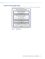
Страница 18: ... alone application Start Device Discovery Toolbelt displays a list of all Extron control devices connected to the network Using the MAC address locate the desired device in the list and select it Network Communication Setup Connect the control processor and PC to the same network Apply power to all devices Use the Set IP feature in Toolbelt or use the Toolbelt Manage Network Settings tab feature t...

Страница 19: ... selected reset mode see Resetting the Unit on page 21 and the reset modes table on page 21 for details IR Learning Receiver In most cases Extron has already produced a driver file for controlling the projector display or source device you plan to use If a device driver file is not available you can create your own using Extron IR Learner Pro software the remote control of the projector or display...

Страница 20: ...o the safe installation of the IPL Pro Series in a rack 1 Elevated operating ambient temperature If installed in a closed or multi unit rack assembly the operating ambient temperature of the rack environment may be greater than room ambient temperature Therefore install the IPL in an environment compatible with the maximum ambient temperature Tma 122 F 50 C specified by Extron 2 Reduced air flow I...

Страница 21: ...G Tx Rx RTS CTS COM 5 LAN PoE IPL PRO S6 IPL PRO S1 LAN PoE POWER 12V 0 3A MAX POWER 12V 0 3A MAX 3 4 2 1 1 G 7 8 6 5 G G S G S INPUT 2 1 2 G S G S 7 8 G S G S 7 8 G S G S 7 8 3 4 5 6 7 8 RELAYS LAN PoE LAN PoE IR SERIAL IPL PRO CR88 IPL PRO IRS8 MAC 00 05 A6 XX XX XX S N E MAC 00 05 A6 XX XX XX S N E MAC 00 05 A6 XX XX XX S N E MAC 00 05 A6 XX XX XX S N E 00 05 A6 XX XX XX MAC 00 05 A6 XX XX XX S...

Страница 22: ...ager la source d alimentation ainsi que l unité If not provided with a power supply this product is intended to be supplied by a UL Listed power source marked Class 2 or LPS and rated output 12 VDC minimum 0 5 A or 48 VDC PoE minimum 0 35 A Si le produit n est pas fourni avec une source d alimentation il doit être alimenté par une source d alimentation certifié UL de classe 2 ou LPS avec une tensi...

Страница 23: ...processor simultaneously The IPL uses PoE when it is available but can switch seamlessly to the external 12 VDC power supply if the PoE connection is dropped ATTENTION Power over Ethernet PoE is intended for indoor use only It is to be connected only to networks or circuits that are not routed to the outside plant or building L alimentation via Ethernet PoE est destinée à une utilisation en intéri...

Страница 24: ... and software flow control Heat Shrink Heat Shrink Over Shield Wires To 5 pole COM port RTS Request to Send CTS Clear to Send Tx Transmitting Data Rx Receiving Data Serial COM Ports Rear Panels 5 pole COM RS 232 RS 422 RS 485 See the Serial Options table for which port supports which standards RS 232 Tx Rx Ground RTS CTS RS 422 Tx Rx Ground Tx Rx RS 485 Ground 5 pole COM Pin Configurations Data pi...

Страница 25: ... 24 of this guide for basic information on configuration Activity LED connector and front panel This yellow LED blinks to indicate network activity Link LED connector and front panel This green LED lights to indicate a good network connection 1000 LED front panel This green LED lights when the unit is connected to a gigabit network connection 1000 LINK ACT LAN PoE I IPL PR PRO S6 5 A6 XX XX XX E 5...

Страница 26: ...among contact input connections Switch Sensor 2 1 3 4 G Heat Shrink Over Shield Wires Ground Device 4 Device 3 Device 2 Device 1 Wire Nut Figure 11 Wiring the Contact Input Ports A 1k ohm pull up resistor in a TTL 5 VDC circuit senses external switch or contact closure After these ports have been configured when the circuit between a signal pin and a ground pin is closed each port can trigger even...

Страница 27: ...relay contacts may be used to control any equipment as long as the contact specifications of a total of 24 V at 1 A are not exceeded for each port These relays are normally open by default When activated the open contacts close They can be set up to operate in one of two ways Latching brief or indefinite period contact press to close press to open or Pulsed timed cycle press to close timeout to op...

Страница 28: ...ts Output options IR 30 kHz to 300 kHz with or without carrier signals Unidirectional RS 232 Figure 14 Wiring the IR Serial Ports Serial control Connect one of these ports to the serial control receive Rx and ground pins of the device to be controlled These ports have the same serial protocol options see page 16 as the COM ports IR control Connect one of these ports directly to the wired IR port o...

Страница 29: ...IPL Pro Series Control Processor Reset Mode Summary Mode Use This Mode to Activation Result Use Factory Firmware Temporarily boot up the unit with factory installed firmware for a single power cycle in the event that a firmware update has failed or if incompatibility issues arise with user loaded firmware To start the Use Factory Firmware reset mode and replace firmware 1 On the control processor ...

Страница 30: ...iate project recovery within 30 seconds after the control processor enters this mode the control processor exits recovery mode Upon exiting project recovery mode The unit returns to its pre recovery mode state and settings The Power LED returns to being steadily lit For devices with firmware version 1 05 and higher To start the Project Recovery reset mode and recover a project 1 On the PC open Glo...

Страница 31: ...r about 6 seconds until the Power LED blinks twice once at 3 seconds again at 6 seconds 2 Release and press the Reset button momentarily for 1 second within 1 second Nothing happens if the momentary press does not occur within 1 second Reset All IP Settings mode Sets the IP address back to factory default 192 168 254 250 Sets the subnet back to factory default 255 255 255 0 Sets the default gatewa...

Страница 32: ...t computer connected to the same network as the control processor See LAN PoE IP connectors and LEDs starting on page 17 for details about LAN port and cabling to connect the control processor to the network Configure the control processor by using the Global Configurator software GC Professional or GC Plus or program it using Global Scripter See the Extron website for full system hardware and sof...

Страница 33: ...puter or mobile device with LinkLicense 3 Save and build the GUI layout file Or Download existing GUI layouts from identical touchpanels Create monitors schedules timers macros and local variables Add touchpanels or other interfaces if used to the project Configure ports on the control processor Import GUI layouts and configure the touchpanels or other interfaces Test the system make adjustments f...

Страница 34: ...other software there is a link for contacting an Extron support representative who can provide you access to the latest version To obtain Extron control product software you must have an Extron Insider account and contact an Extron support representative Extron provides training to our customers on how to use the software For Global Configurator Professional you must first attend Extron training p...

Страница 35: ... link in the row for the product you want to control to download the driver or to download the communication sheet The communication sheet provides details that may be helpful for working with the product and its control driver 4 For some software you can click the Download or Download Now button to begin downloading the software file For other software such as Global Configurator in GC Profession...

Страница 36: ...ep by step instructions for typical configuration tasks Obtain network addresses and related information from your network administrator Set up the IP address for the control processor See Network Communication Setup on page 10 for an overview of how to set up the network properties of the unit For details see the GC help file or Toolbelt help file which contains instructions on how to set the IP ...

Страница 37: ...respond as expected check the following Power Connections Ensure that all devices are plugged in Make sure that each device is receiving power The IPL front panel power LED lights if the device is receiving power Data Connections 1 Check the cabling connections and make adjustments as needed The Link LEDs on the IPL and on the touchpanel or PC should be lit solid green if a network connection is d...

Страница 38: ...tly over the IR pickup window on the controlled device Verify that the appropriate drivers were used while creating the GC Professional or GC Plus configuration file and that the correct commands and signal types IR RS 232 Ethernet are associated with the appropriate ports on the IPL and on the other devices Verify that input current at any contact input port does not exceed 250 mA If you are stil...

Страница 39: ...sted package license in the License Information window click the link in the License column for the relevant package This opens a copy of the package license in a separate window A list of licenses is also available in the Pro Series Control Product Network Ports and Licenses Guide at www extron com File Types a Key to Extron specific File Names A basic understanding of the types of files used by ...

Страница 40: ...enhanced Electronic Mail and der file types PEM file types are ASCII encoded and are the required format for uploading to the control processor DER Distinguished Encoding Rules file types are binary encoded and can typically have several file extension variations such as crt and cer There are many standard tools that can convert from DER to PEM file encodings if needed NOTE A DER format file must ...

Страница 41: ...Configurator in either GC Professional or GC Plus mode and open the Toolbelt link or open the Toolbelt software directly 2 Either add the desired control processor manually or start device discovery and select the desired processor from the list of discovered devices 3 Click Manage in the row for the desired control processor and view the device information that appears in that section Using a Bro...

Страница 42: ...file exe from the website and run the installer program The program automatically stores the firmware file on the PC in C Program Files Extron Firmware within a folder specific to that version 3 Write down the firmware filename and location for later use The filename ends in eff such as 49 247 50 x xx xxxx yyyy eff where x xx xxxx is the version number NOTE The firmware update file must have a fil...

Страница 43: ...ab Emirates Dubai This Limited Warranty does not apply if the fault has been caused by misuse improper handling care electrical or mechanical abuse abnormal operating conditions or if modifications were made to the product that were not authorized by Extron NOTE If a product is defective please call Extron and ask for an Application Engineer to receive an RA Return Authorization number This will b...

Отзывы: